I/O configuration variants
6.7 Connection of two-channel I/O to the PROFIBUS DP interface
CPU 410 Process Automation/CPU 410 SMART
92 System Manual, 05/2017, A5E31622160-AC
Redundant analog input modules with non-redundant encoder
With non-redundant encoders, analog input modules are used in a 1-out-of-2 configuration:
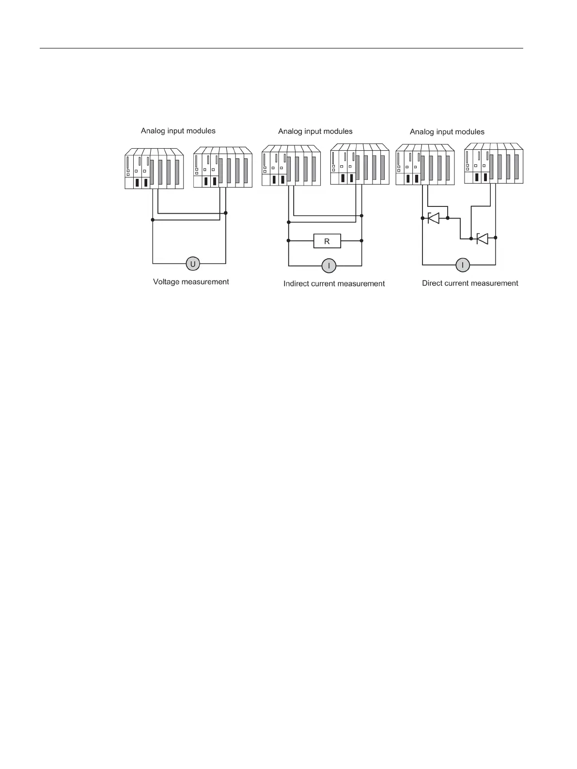
Figure 6-17 Fault-tolerant analog input modules in 1-out-of-2 configuration with one encoder
Remember the following when connecting an encoder to multiple analog input modules:
● Connect the analog input modules in parallel for voltage sensors (left in figure).
● You can convert a current into voltage using an external load to be able to use voltage
analog input modules connected in parallel (center in the figure).
● 2-wire transmitters are powered externally to allow you to repair the module online.
The redundancy of the fail-safe analog input modules enhances their availability.
If you do not use terminal modules, see the interconnection examples in the Appendix
Connection examples for redundant I/Os (Page 391).
Redundant analog input modules for indirect current measurement
The following applies to the wiring of analog input modules:
● Suitable encoders for this circuit are active transmitters with voltage output and
thermocouples.
● The "wire break" diagnostics function in HW Config must not be enabled either the
modules are operated with transmitters or when thermocouples are connected.
● Suitable encoder types: active 4-wire and passive 2-wire transmitters with output ranges
+/-20 mA, 0 to 20 mA, and 4 to 20 mA. 2-wire transmitters are powered by an external
auxiliary voltage.
● Criteria for the selection of resistance and input voltage range are the measurement
accuracy, number format, maximum resolution and possible diagnostics.
● In addition to the options listed, other input resistance and voltage combinations
according to Ohm’s law are also possible. However, note that the number format,
diagnostic capability and resolution may then be lost. The measurement error also
depends largely on the size of the measure resistance of certain modules.
● Use a measure resistance with a tolerance of +/- 0.1% and TC 15 ppm.
 Loading...