I/O configuration variants
6.7 Connection of two-channel I/O to the PROFIBUS DP interface
CPU 410 Process Automation/CPU 410 SMART
90 System Manual, 05/2017, A5E31622160-AC
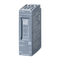
Using redundant digital input modules with redundant encoders
With redundant encoders, you use digital input modules in a 1-out-of-2 configuration:
Figure 6-15 Fault-tolerant digital input modules in 1-out-of-2 configuration with two encoders
The use of redundant encoders also increases their availability. A discrepancy analysis
detects all errors, except for the failure of a non-redundant load voltage supply. You can
enhance availability by installing redundant load power supplies.
You will find interconnection examples in Appendix Connection examples for redundant I/Os
(Page 391).
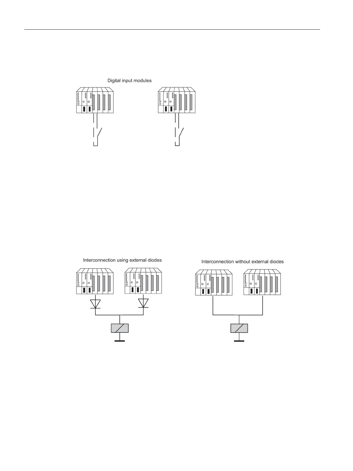
Redundant digital output modules
Fault-tolerant control of a final controlling element can be achieved by connecting two
outputs of two digital output modules or fail-safe digital output modules in parallel (1-out-of-2
configuration).
Figure 6-16 Fault-tolerant digital output modules in 1-out-of-2 configuration
The digital output modules must be connected to a common load voltage supply.
If you do not use terminal modules, see the interconnection examples in the Appendix
Connection examples for redundant I/Os (Page 391).
 Loading...