Configuration of the CPU 410
3.3 Status and error displays
CPU 410 Process Automation/CPU 410 SMART
42 System Manual, 05/2017, A5E31622160-AC
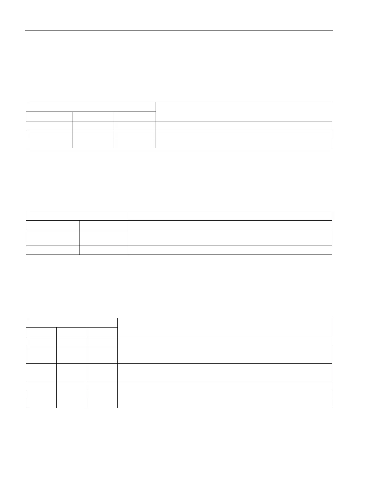
MSTR, RACK0, and RACK1 LEDs
The three LEDs MSTR, RACK0, and RACK1 provide information about the rack number set
on the CPU and show which CPU controls the switched I/O.
Table 3- 3 Possible states of the MSTR, RACK0 and RACK1 LEDs
CPU controls switched I/O
Irrelevant Dark Lit CPU on rack number 1
The two INTF and EXTF LEDs provide information about errors and other particular things
that happen during user program execution.
Table 3- 4 Possible states of the INTF and EXTF LEDs
Lit Irrelevant An internal error was detected (programming, parameter assignment, or license
An external error has been detected (i.e. an error not caused by the CPU)
BUS1F, BUS5F, and BUS8F LEDs
The BUS1F, BUS5F and BUS8F LEDs indicate errors associated with the PROFIBUS DP
interface and the PROFINET IO interfaces.
Table 3- 5 Possible states of the BUS1F, BUS5F, and BUS8F LEDs
An error was detected on the PROFIBUS DP interface X1.
Irrelevant Lit Irrelevant An error was detected on the first PROFINET IO interface X5.
A PROFINET IO system is configured but not connected.
Irrelevant Irrelevant Lit An error was detected on the second PROFINET IO interface X8.
A PROFINET IO system is configured but not connected.
One or more devices on the first PROFINET IO interface X5 is not responding.
One or more devices on the second PROFINET IO interface X8 is not responding.
One or more slaves on the PROFIBUS DP interface X1 is not responding.
 Loading...