I/O configuration variants
6.7 Connection of two-channel I/O to the PROFIBUS DP interface
CPU 410 Process Automation/CPU 410 SMART
System Manual, 05/2017, A5E31622160-AC
93
Additional conditions for specific modules
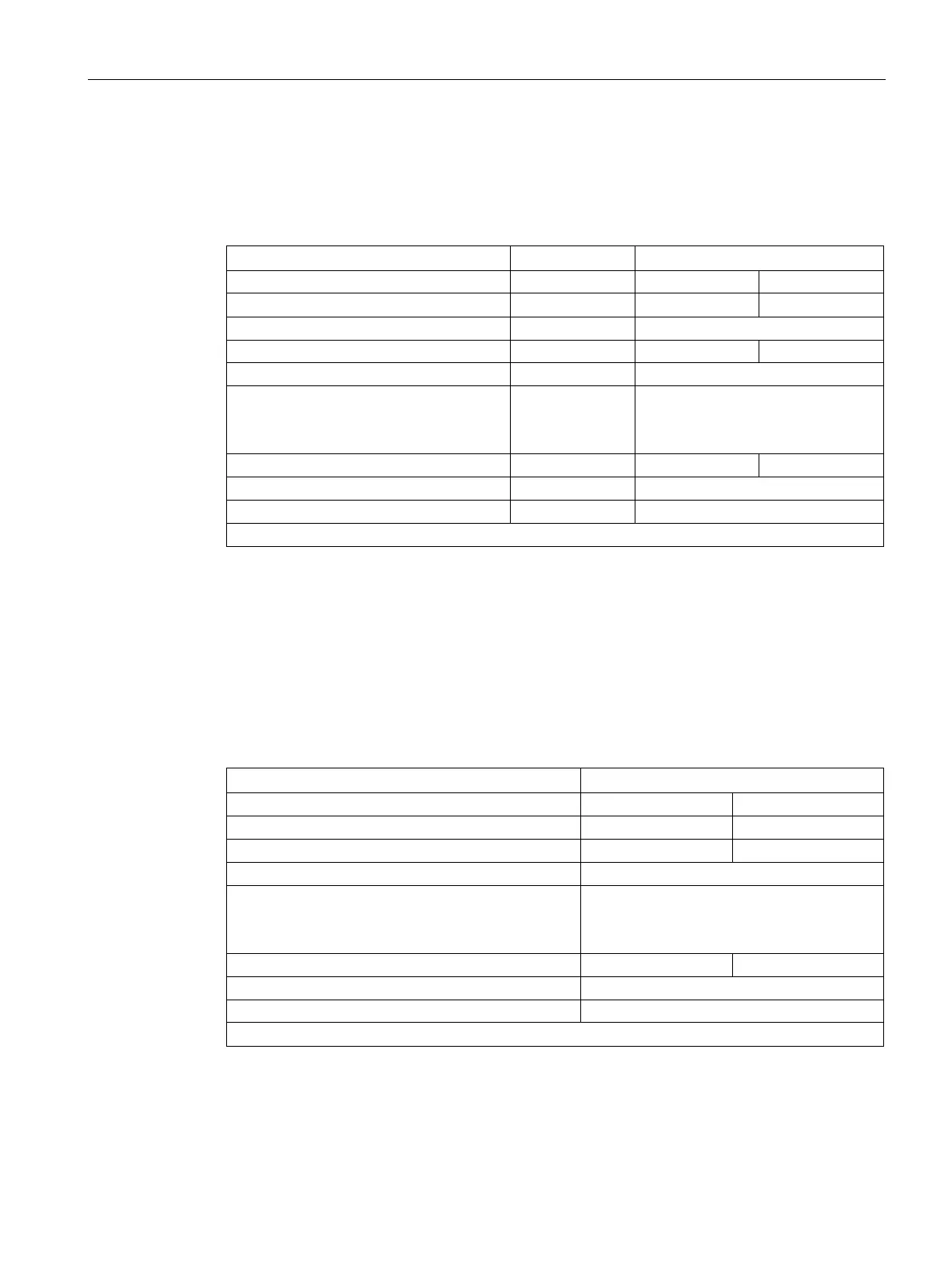
AI 8x12 bit 6ES7 331-7K..02-0AB0
● Use a 50 ohm or 250 ohm resistor to map the current on a voltage:
Input range to be assigned +/-1 V +/-5 V 1...5 V
Measuring range cube position
Circuit-specific measuring error
- 2 parallel inputs
-
-
0.5%
0.25%
Load for 4-wire transmitters
Input voltage for 2-wire transmitters
*) The AI 8x12bit outputs diagnostic interrupt and measured value "7FFF" in the event of wire break.
The listed measuring error results solely from the interconnection of one or two voltage
inputs with a measure resistance. Allowance has neither been made here for the tolerance
nor for the basic/operational limits of the modules.
The measuring error for one or two inputs shows the difference in the measurement result
depending on whether two inputs or, in case of error, only one input acquires the current of
the transmitter.
AI 8x16 bit 6ES7 331-7NF00-0AB0
● Use a 250 ohm resistor to map the current on a voltage:
Input range to be assigned
Circuit-specific measuring error
- 2 parallel inputs
-
-
Load for 4-wire transmitters
Input voltage for 2-wire transmitters
*) It may be possible to use the freely connectible internal module 250 ohm resistors
 Loading...