14-9
Equipment
Manual OP7, OP17
Release 04/99
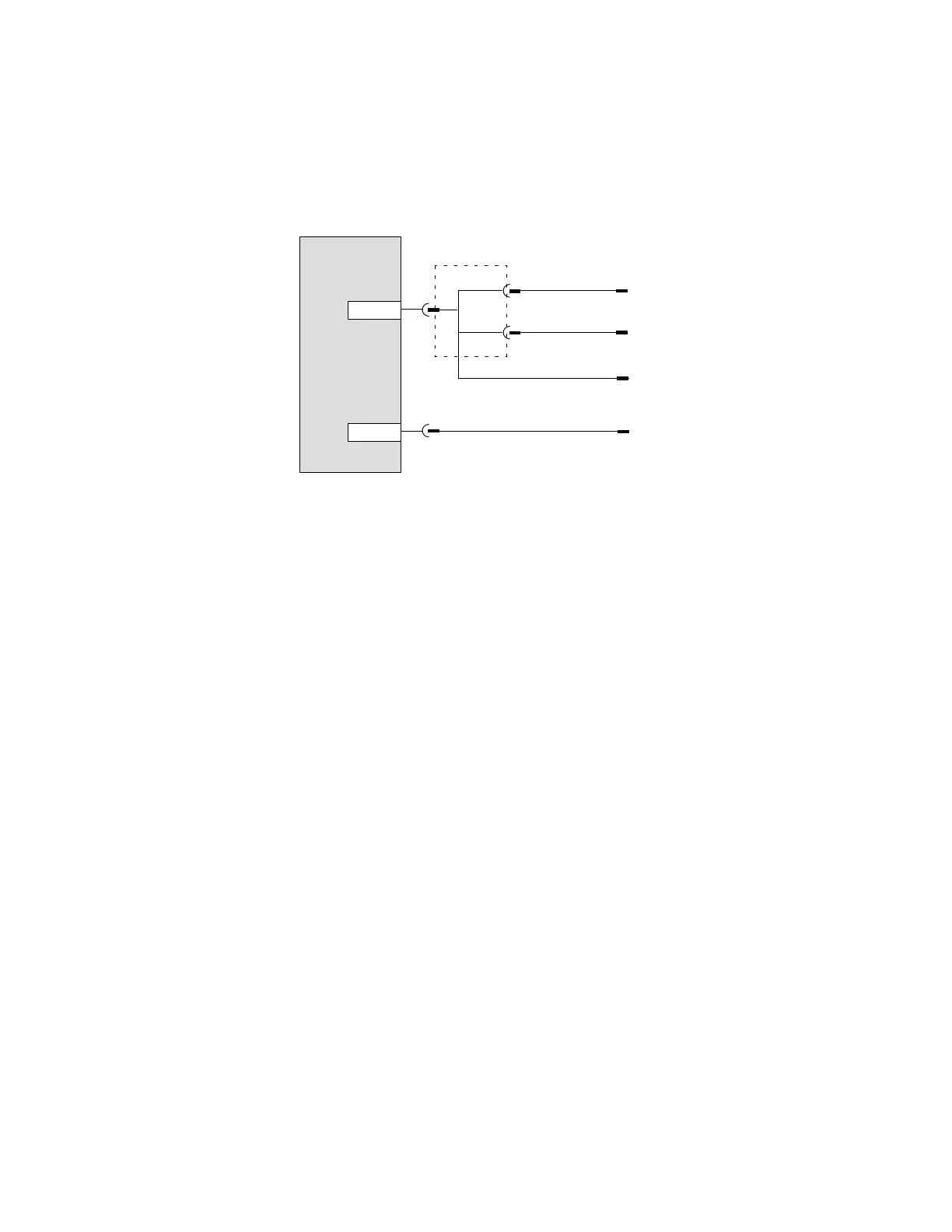
14.2.5 Connecting a Printer
Figure
14-5 shows you how to connect a printer to an OP7 and an OP17.
A printer is always connected to the PU interface of the OP
. T
o do this,
disconnect the PU.
IF1A
Operator
Panel
TTY/RS232
IF2
OP7
OP17
TTY/RS232
Printer
Printer
Printer
PLC
TTY/RS232
RS232
Y cable
Figure 14-5 Connection Configuration Scheme for Printers
If
the OP is connected to the PLC through a TTY or RS232 interface, a
Y cable is required for simultaneous operation of a printer
. The PLC and
printer
, in this case, are operated with physically dif
ferent interfaces.
For attaching Siemens printers, there are standard cables available (refer to
Catalog No. ST80.1). For other printers, you have to use the cables supplied
or specially manufactured ones.
Y
ou will find the pin assignments of the plug connectors in appendix D of
this manual.
The OP makes the following print functions available:
hardcopy
printout of screens
printout of alarm or event buf
fer
direct message logging
printout on buffer overload
printout of data records
printout of recipe directory
printout of screen directory
Connection
Configuration
Scheme
Print functions

 Loading...