D-1
Equipment
Manual OP7, OP17
Release 04/99
Interface Assignment
Table
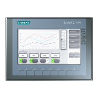
D-1 shows the interface configuration of the dif
ferent OPs. Entries D-2
to D-5 refer to the corresponding pin assignments in T
ables D-2 to D-5.
Table D-1 Interface assignment OP7 and OP17
OP
version
Interface OP7
PP
OP7
DP
OP7
DP-12
OP17
PP
OP17
DP
OP17
DP-12
IF1A D-2 D-2 D-2 D-2 D-2 D-2
IF1B D-3 D-4 D-5 D-3 D-4 D-5
IF2 – – – D-2 D-2 D-2
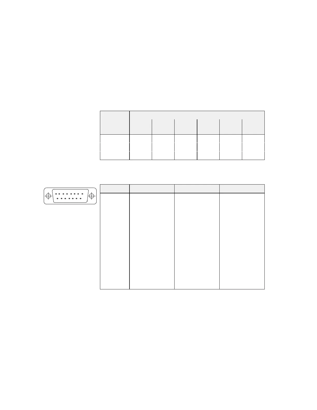
Table D-2 Pin assignment 15-pin sub-D socket
Pin General RS232 TTY
1
2
3
4
5
6
7
8
9
10
11
12
13
14
15
n.c.
n.c.
GND
+5 V
GND
RxD
TxD
CTS
RTS
RxD–
TxD+
TxD–
RxD+
+20 mA
1)
+20 mA
1)
1) Not with IF2
Overview
D
81
15 9

 Loading...