1-5
S7-200 Programmable Controller, CPU 210
C79000-G7076-C235-01
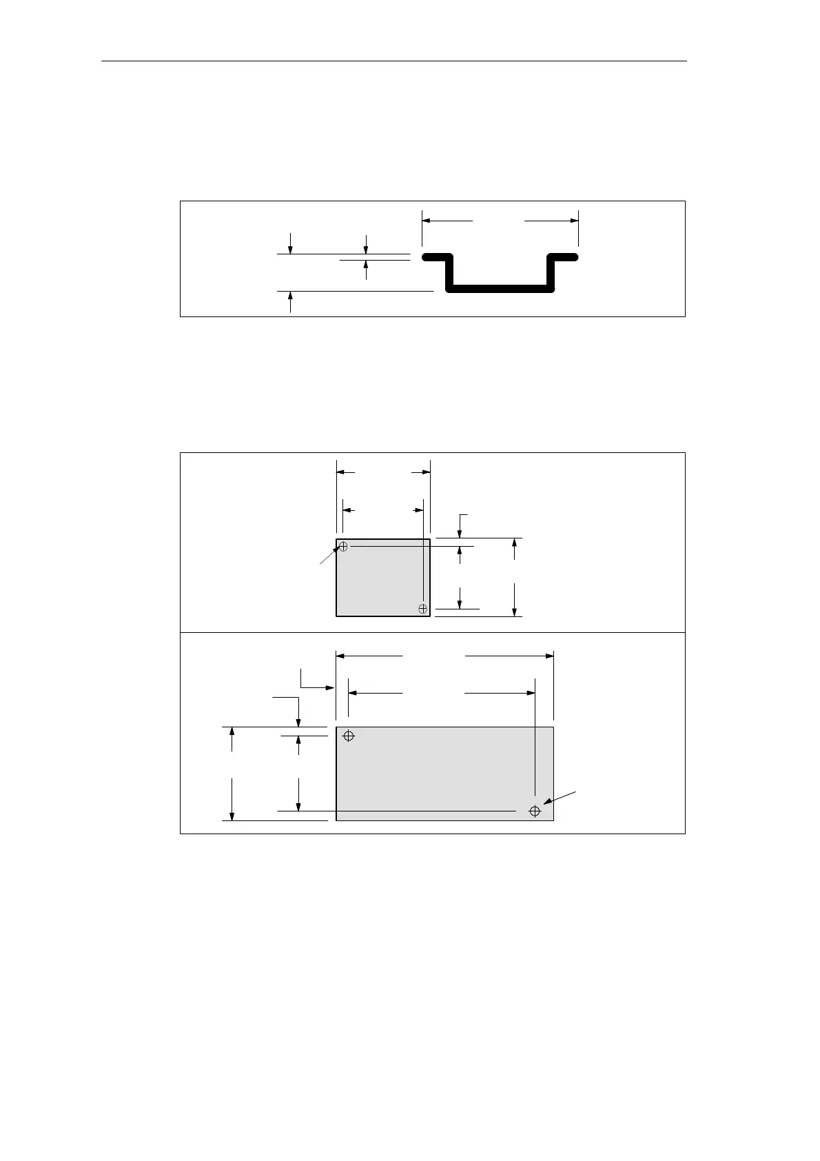
DIN Rail Requirements
The CPU 210 can be installed on a standard DIN rail (DIN EN 50 022). Figure 1-5 shows the
dimensions for this DIN rail.
35 mm
(1.38 in.)
1.0 mm
(0.039 in.)
7.5 mm
(0.29 in.)
Figure 1-5 DIN Rail Dimensions
Panel-Mounting Dimensions
The CPU 210 and the PDS 210 include mounting holes to facilitate installation on panels.
Figure 1-6 provides the mounting dimensions.
6.4 mm
(0.25 in.)
77.3 mm
(3.04 in.)
CPU 210
Mounting Holes
(M4 or no. 8)
80 mm
(3.15 in.)
67.3 mm
(2.65 in.)
90 mm
(3.54 in.)
6.4 mm
(0.25 in.)
184.3 mm
(7.25 in.)
Program Development Station
(PDS 210)
Mounting Holes
(M4 or no. 8)
197 mm
(7.76 in.)
6.4 mm
(0.25 in.)
80 mm
(3.15 in.)
67.3 mm
(2.65 in.)
Figure 1-6 Mounting Dimensions for the CPU 210 and PDS 210
Installing the S7-200 CPU 210

 Loading...


