3-26
S7-200 Programmable Controller, CPU 210
C79000-G7076-C235-01
Turning the LED On and Off
The program uses a timer (T1) and the pattern stored in MW3 to turn the LED on and off. The
program increments MW1 to count the number of passes through the control logic for flashing
the lights; after 10 passes, the MW1 is reset to 0.
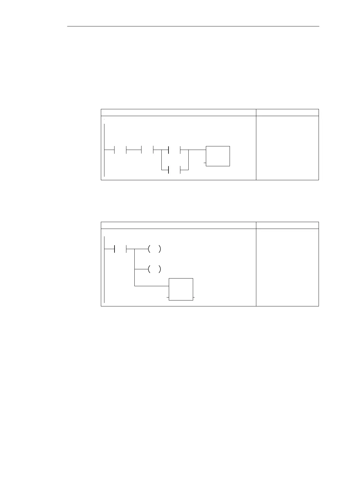
Figure 3-25 shows the control logic for starting the timer. The timer starts when the system is
armed, the light-blink timer bit is not set, and either Zone 1 or Zone 2 opens.
Network 9
LAD STL
TON
IN
PT
T1
+0
M0.7
/
NETWORK
LDN M0.7
AN I0.2
LDN I0.0
ON I0.1
TON T1, +0
If the light-blink timer bit is not set, and the system is
armed, start the light-blink timer when either Zone 1 or
Zone 2 becomes open.
I0.2
/
I0.0
/
I0.1
/
Figure 3-25 Control Logic for Starting the Light-Blink Timer
Figure 3-26 shows the control logic for incrementing the count for the number of times that
the light-blink logic has been performed.
LAD STL
Network 10
NETWORK
LDW>= T1, +4
= M0.7
R M0.0, 1
INCW MW1
If the light-blink timer is less than or
equal to 400 ms, then set the light-blink
timer bit, reset the LED bit, and
increment the step counter.
T1
>=I
+4
M0.7
INC_W
EN
IN OUTMW1 MW1
M0.0
R
1
Figure 3-26 Control Logic for Setting the Timer Bit and Incrementing the Counter
Figure 3-27 shows the control logic for turning the LED on and off. Each pass through the
light-blink logic evaluates a different bit of MW3 (M4.0 to M4.7). Based on the pattern loaded
(see Figure 3-24), the LED turns on or off.
Figure 3-28 shows the control logic for resetting the count.
Getting Started with a Sample Program