3-23
S7-200 Programmable Controller, CPU 210
C79000-G7076-C235-01
3.8 Downloading and Monitoring the Sample Program
Once you have downloaded your program to the PDS 210, you can use the Debug features
to monitor or debug the operation of your program.
Downloading the Project to the PDS 210
The PDS 210 must be in STOP mode for you to download a program. To download your
program, select the menu command Project
"
Download... . An information message tells
you whether or not the download operation was successful.
Note
STEP 7-Micro/WIN does not verify that your program uses memory or I/O addresses that
are valid for the PDS 210 or the CPU 210. If you attempt to download a program that uses
invalid addresses or program instructions that are not supported by the PDS 210, the
PDS 210 rejects the attempt to download the program and displays an error message.
You must ensure that all memory locations, I/O addresses, and instructions used by your
program are valid for the PDS 210 and CPU 210.
Using the Ladder Editor to Monitor the Status of the Program
Ladder status shows the current state of events in your program. Reopen the Ladder Editor
window, if necessary, and select the menu command Debug
"
Ladder Status On.
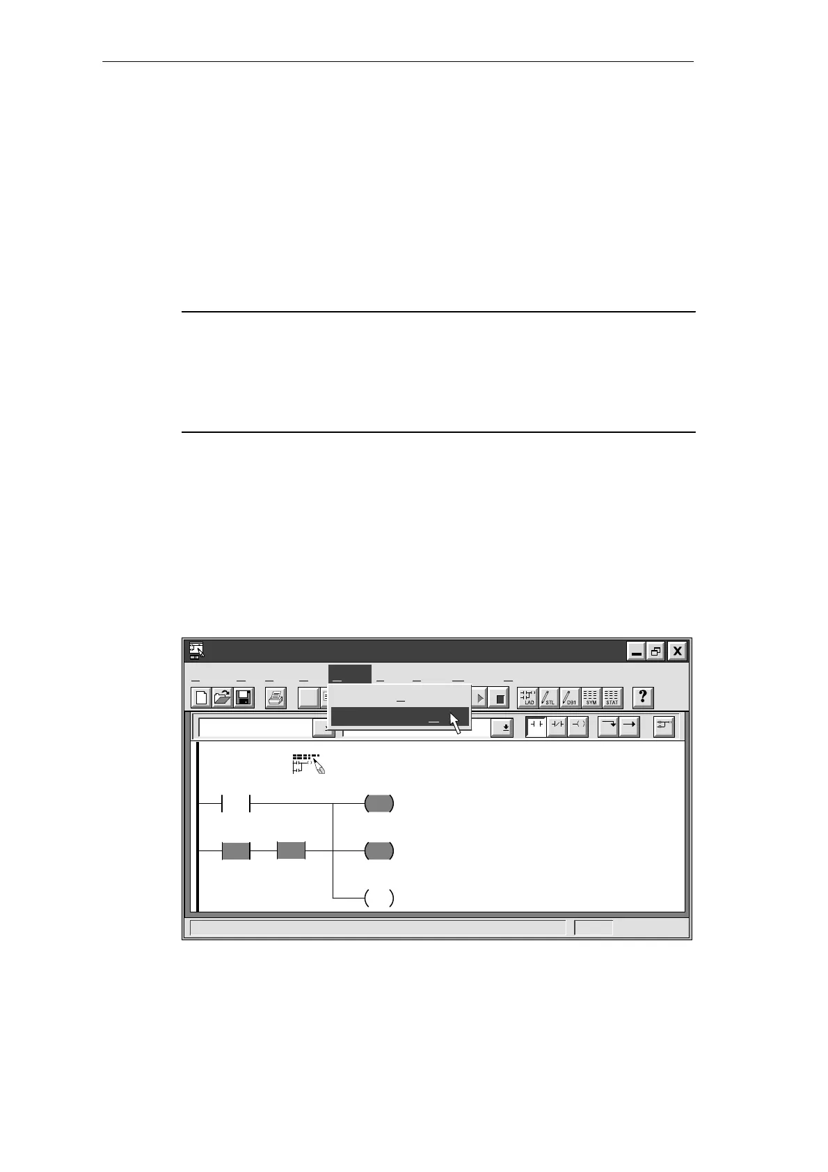
If you have an input simulator connected to the input terminals on your CPU, you can turn on
switches to see power flow and logic execution. For example, if you turn on switch I0.2, the
power flow for Network 1 will be complete when timer T0 is greater than or equal to 600. The
network will look like the one shown in Figure 3-22: M0.1 and Q0.3 are set to 1, and M0.2 is
reset to 0.
✂
Project Edit View CPU Debug Tools Setup Window Help
STEP 7-Micro/WIN - c:\microwin\house.prj
Contacts Normally Open
F4 F5 F8F7F6 F10
F3F2
Debug
Execute Scans...
Ladder Status O
n
T0
>=I
+600
I0.3
I0.2
M0.1
S
1
Q0.3
S
1
M0.2
R
Sound the alarm!
Network 1
Figure 3-22 Monitoring Status of the First Network
Getting Started with a Sample Program

 Loading...


