3-2
S7-200 Programmable Controller, CPU 210
C79000-G7076-C235-01
3.1 Defining the Requirements for the Application Example
Defining the Inputs and Outputs for the Application
This chapter describes a sample program for a home security system. As shown in
Figure 3-2, the program monitors two zones. Any breach of security results in an alarm being
sounded. The sample program uses the following inputs:
S Input 1 (I0.0) monitors zone 1 (entrance, living room, kitchen, and bedroom 3).
S Input 2 (I0.1) monitors zone 2 (bedroom 1, bedroom 2, bathroom, and rear entrance).
S Input 3 (I0.2) provides the arm/disarm switch for the security system.
S Input 4 (I0.3) provides a “panic button” to immediately turn on the alarm siren.
In addition to the inputs, the program uses the following outputs.
S Output 1 (Q0.0) controls the LED on the security system.
S Output 2 (Q0.1) turns on the siren to sound an alarm.
S Output 3 (Q0.2) turns on a low-level notification alert to signify that the alarm will be
turned on in a predetermined number of seconds.
S Output 4 (Q0.3) turns on an external interface relay (perhaps to an automatic dialing
machine).
Figure 3-3 shows a wiring diagram for the home security application.
Creating Symbolic Names for the Elements of the Program
Symbolic names help to document or define the specific memory locations or I/O used by
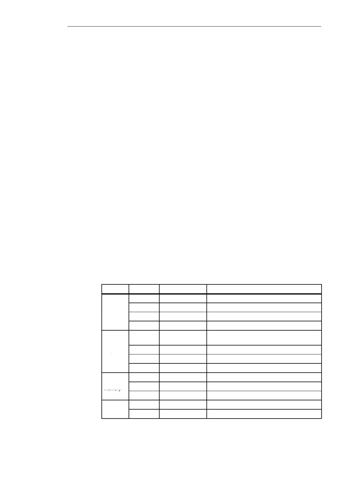
your program. Table 3-1 lists the symbolic names used by the program for the sample
application. The sample program also uses SM0.5 to generate an on/off (blinking) pattern for
the LED.
Table 3-1 Symbolic Names for the Application Example
Element Address Symbolic Name Description
I0.0 Zone_1 Normally Closed input for Zone 1
I0.1 Zone_2 Normally Closed input for Zone 2
u
I0.2 Armed Armed = closed, and disarmed = open
I0.3 Panic_Alarm Normally Open input for panic alarm
Q0.0 LED System LED (on if armed, or flashing if disarmed and
zone 1 or zone 2 open)
Outputs
Q0.1 Alarm High-level alarm (siren)
Q0.2 Low_Alert Low-level alert to disarm system
Q0.3 Modem Relay to start the modem dialer unit
M0.0 LED_Bit Stores the status for the LED
Internal
Memory
M0.1 Alarm_Bit Stores the status for the alarm
M0.2 Low_Bit Stores the status for the low-level alert
T0 Alert_Timer Provides a delay before the alarm turns on
T2 Exit_Timer Delay time after arming the system
Getting Started with a Sample Program