3-25
S7-200 Programmable Controller, CPU 210
C79000-G7076-C235-01
3.9 Modifying the Sample Program
You can use the following networks of control logic to modify the sample program. These
networks provide the following enhancements to the sample program:
S If Zone 1 is open, the LED flashes one time.
S If Zone 2 is open, the LED flashes two times.
S If both zones are open, the LED flashes three times (one short flash, followed by a pause
and then two short flashes).
The modified program uses the memory addresses shown in Table 3-3. If you used symbolic
addressing with your program, add these symbolic names and addresses to the Symbol
Table.
Table 3-3 Memory Locations Used to Modify the Sample Program
Element Address Symbolic Name Description
M0.7 Blink_Bit Stores the status for the LED
Internal
Memory
MW1 Step_Counter Tracks the blinking of the LED
MW3 Blink_Pattern Stores the pattern for flashing the LED on and off
Timers T1 Blink_Timer Increments the step counter
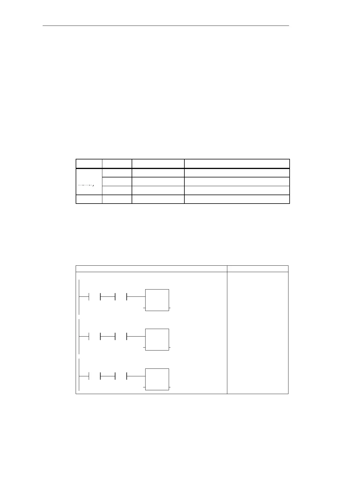
Creating the Blink Patterns for the LED
The program uses different bit patterns as the basis for the logic that turns the LED on and
off. Based on the condition, the program loads a value into the word that stores the blink
pattern. Figure 3-24 shows the networks that move the bit patterns into MW3. Use
STEP 7-Micro/WIN to enter the networks into the program.
NETWORK
LDN I0.0
A I0.1
MOVW +231, MW3
LAD STL
Network 6
I0.1I0.0
/
If Zone 1 is open and Zone 2 is closed, then load the
value 231 (1110011100) in MW3
MOV_W
EN
IN OUT+231 MW3
Network 7
I0.1
/
I0.0
MOV_W
EN
IN OUT+165 MW3
Network 8
I0.1
/
I0.0
/
MOV_W
EN
IN OUT+167 MW3
If Zone 1 is closed and Zone 2 is open, then load the
value 165 (1010010100) in MW3
If both Zone 1 and Zone 2 are open, then load the value
167 (1110010100) in MW3
NETWORK
LD I0.0
AN I0.1
MOVW +165, MW3
NETWORK
LDN I0.0
AN I0.1
MOVW +167, MW3
Figure 3-24 Control Logic for Lamp Operations
Getting Started with a Sample Program