Getting Started
A5E36037886-003, 04/2017
75
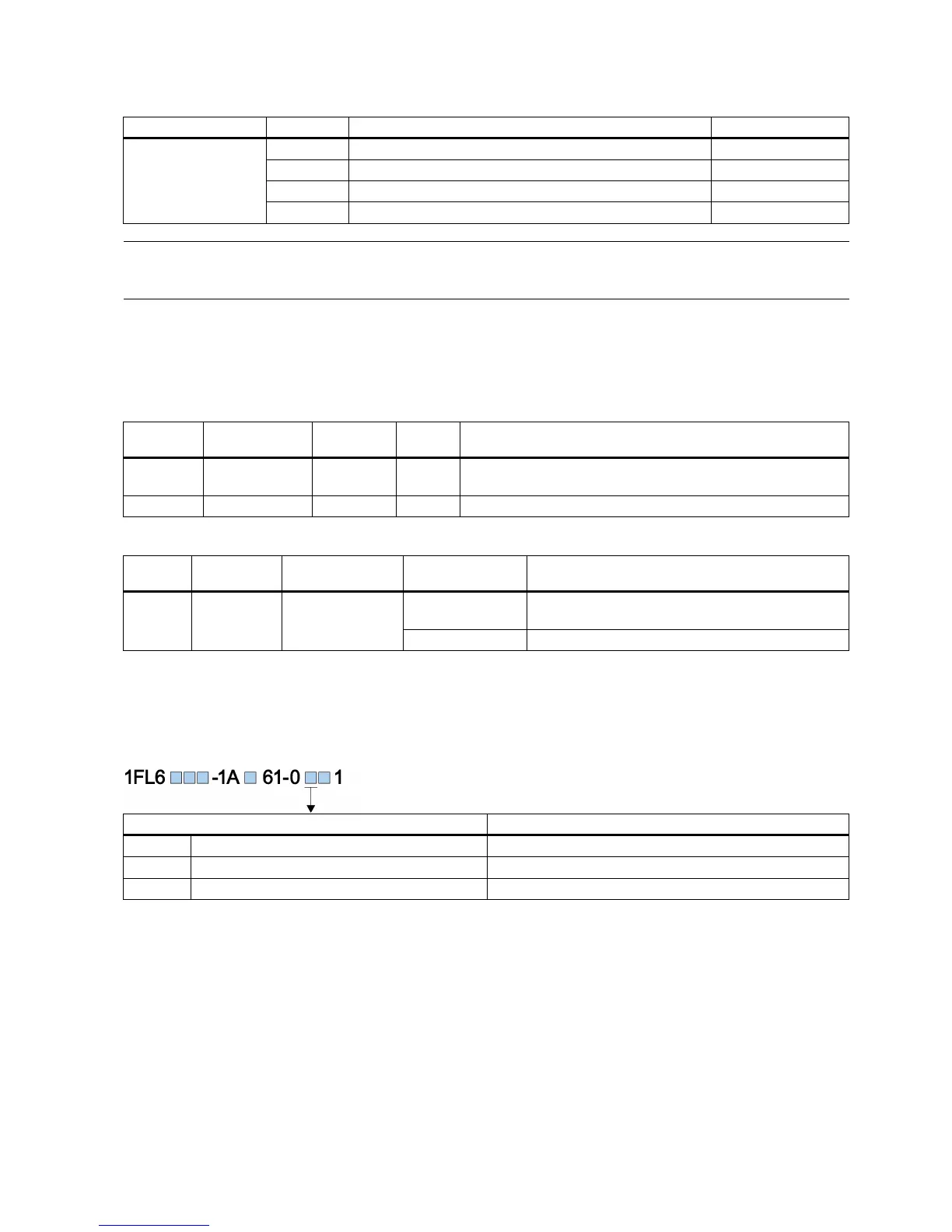
You can select one of the setpoint pulse train input forms by setting the parameter p29010:
Setpoint pulse train input form
Pulse + Direction, positive logic
Pulse + Direction, negative logic
Note
After modifying parameter p29010, you must perform referencing again because the reference point will lost after p29010
changes.
When the deviation between the position setpoint and the actual position is within the preset in-position range specified in
p2544, the signal INP (in position) is output.
40 (default) LU Position window (in-position range)
p29332 1 to 13 3 - Digital output 3 assignment
DO INP X8-32 (factory
setting)
1 Number of droop pulses is in the preset in-position
range (parameter p2544)
Droop pulses are beyond the in-position range
Calculating electronic gear ratio
Encoder specifications
The encoder specifications are shown as follows:
20-bit + 12-bit multi-turn
With the function of electronic gear, you can define the motor revolutions according to the number of setpoint pulses, and
sequentially define the distance of mechanical movement. The minimum travelling distance of load shaft according to one
setpoint pulse is called a length unit (LU); for example, one pulse results in 1 µm movement.

 Loading...


