SIMOTION D4x5-2
Commissioning and Hardware Installation Manual, 02/2012
347
Diagnostics
8
8.1 Diagnostics via LED displays
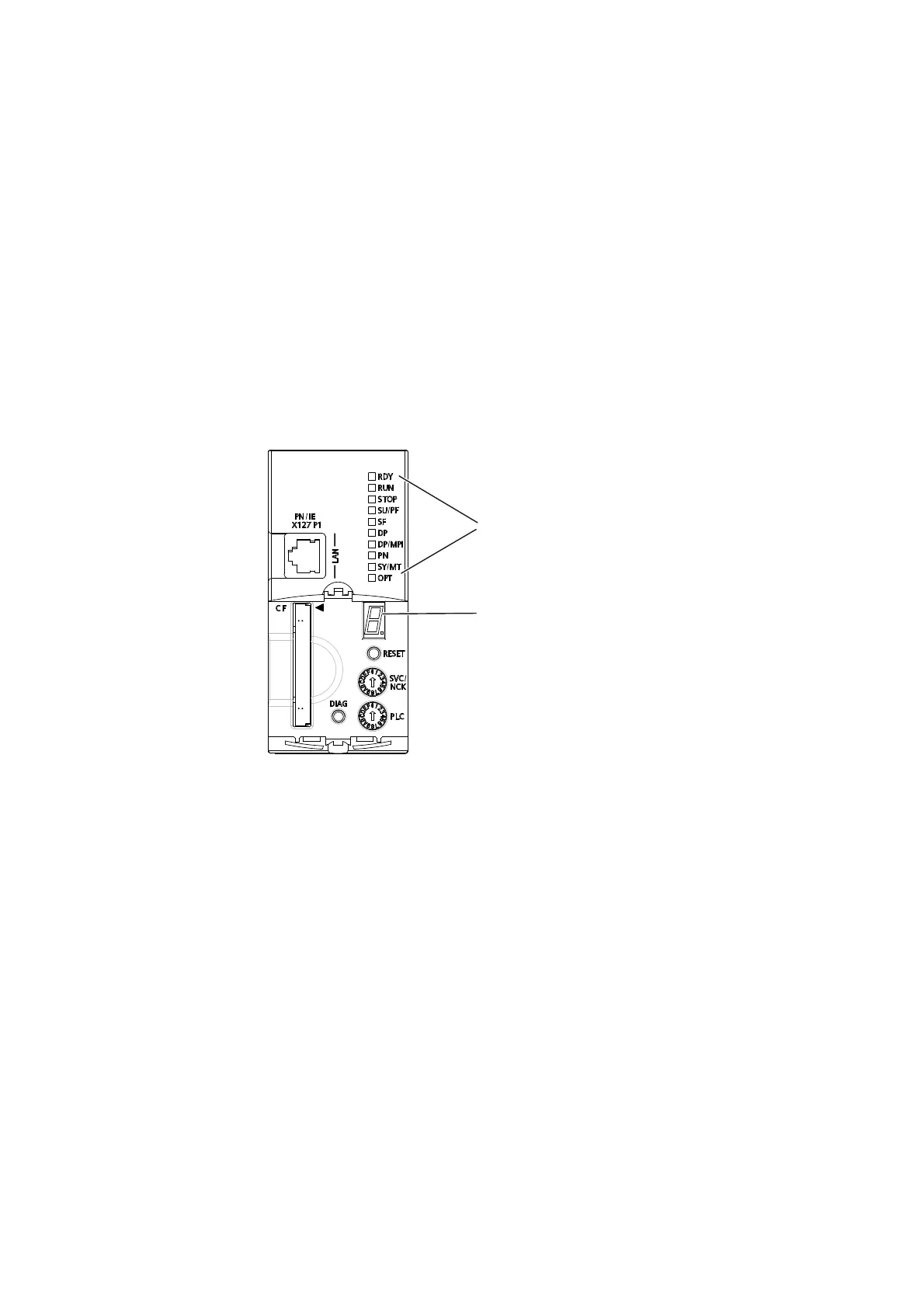
Arrangement of LED displays
The front side of the SIMOTION D4x5-2 has ten LED displays arranged vertically in a row.
There is also a 7-segment display below the blanking cover.
/('GLVSOD\V
[
VHJPHQWGLVSOD\
Figure 8-1 7-segment and LED displays on the D4x5-2
LED status key
The LED displays indicate the different operating modes and any errors occurring on the
SIMOTION D4x5-2. They do so by illuminating, flashing, or flickering in different colors.
The following tables provide an overview of all occurring LED display combinations.
Symbols in the tables for states of the LEDs:
● 1 = LED on
● 0 = LED off
● 0.5/1 = flashing LED (0.5 Hz)
● 2/1 = flashing LED (2 Hz)
● Λ = flickering LED
● X = LED can light up
 Loading...


