Additional system components
7.1 Option Board: Communication Board Ethernet CBE20
SINAMICS DCM DC Converter
Operating Instructions, 12/2018, A5E34763375A
195
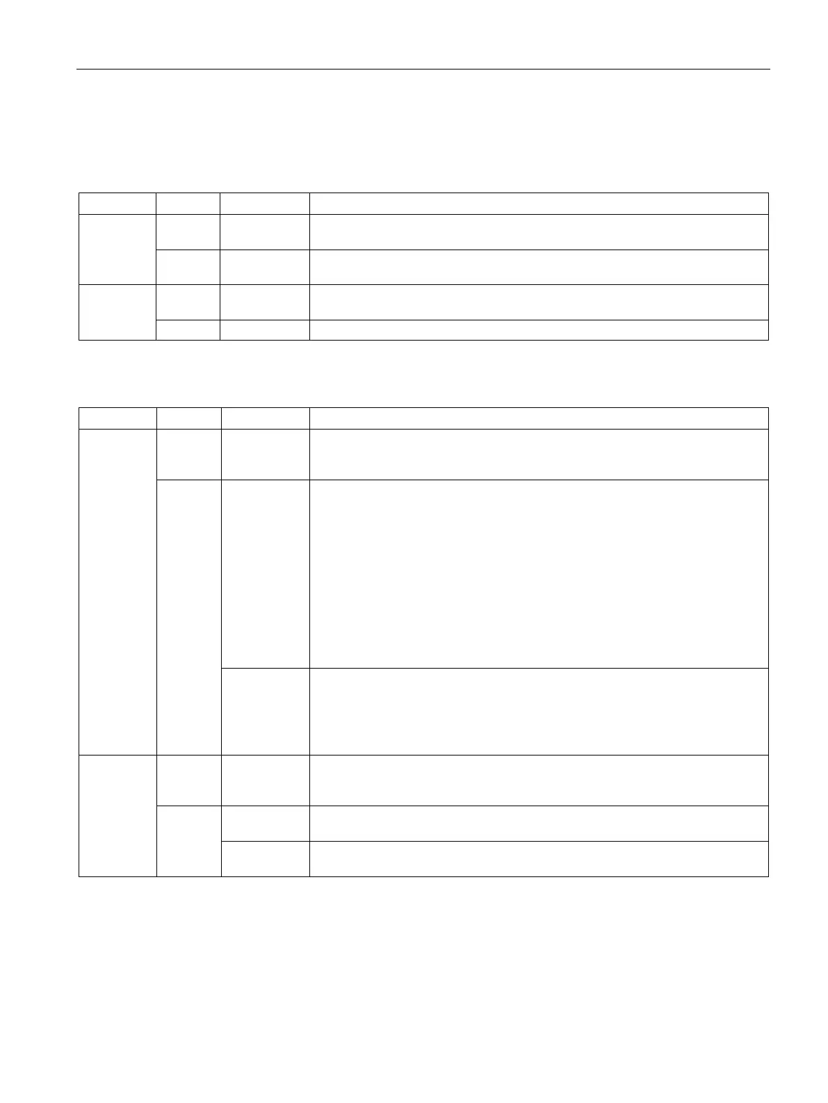
Table 7- 2 Meaning of the LEDs at ports 1 to 4 of the X1400 interface
Link port - Off Electronics power supply is missing or outside permissible tolerance range
(link missing or defective).
Green Continuous
light
A different device is connected to port x and a physical connection exists.
Activity port - Off Electronics power supply is missing or outside permissible tolerance range
Data is being received or sent at port x.
Table 7- 3 Meaning of the Sync and Fault LEDs on the CBE20
Fault – Off If the link port LED is green:
The CBE20 is operating normally, data is being exchanged with the configured
Red Flashing light
• The response monitoring interval has elapsed.
• Communications is interrupted.
• The IP address is incorrect.
• Incorrect or no configuration.
• Incorrect parameter settings.
• Incorrect or missing device name.
• IO Controller not connected/switched off, although an Ethernet connection
has been established.
• Other CBE20 errors
Continuous
light
CBE20 bus error
• No physical connection to a subnet/switch.
• Incorrect transmission rate
• Full duplex transmission is not activated.
Sync – Off If the link port LED is green:
Control Unit task system is not synchronized with the IRT clock. An internal
substitute clock is generated.
Green Flashing light Control Unit task system has synchronized with the IRT clock and data is being
Continuous
Task system and MC-PLL have synchronized with the IRT clock.

 Loading...


