Additional system components
7.2 SMC10 Sensor Module Cabinet-Mounted
SINAMICS DCM DC Converter
Operating Instructions, 12/2018, A5E34763375A
201
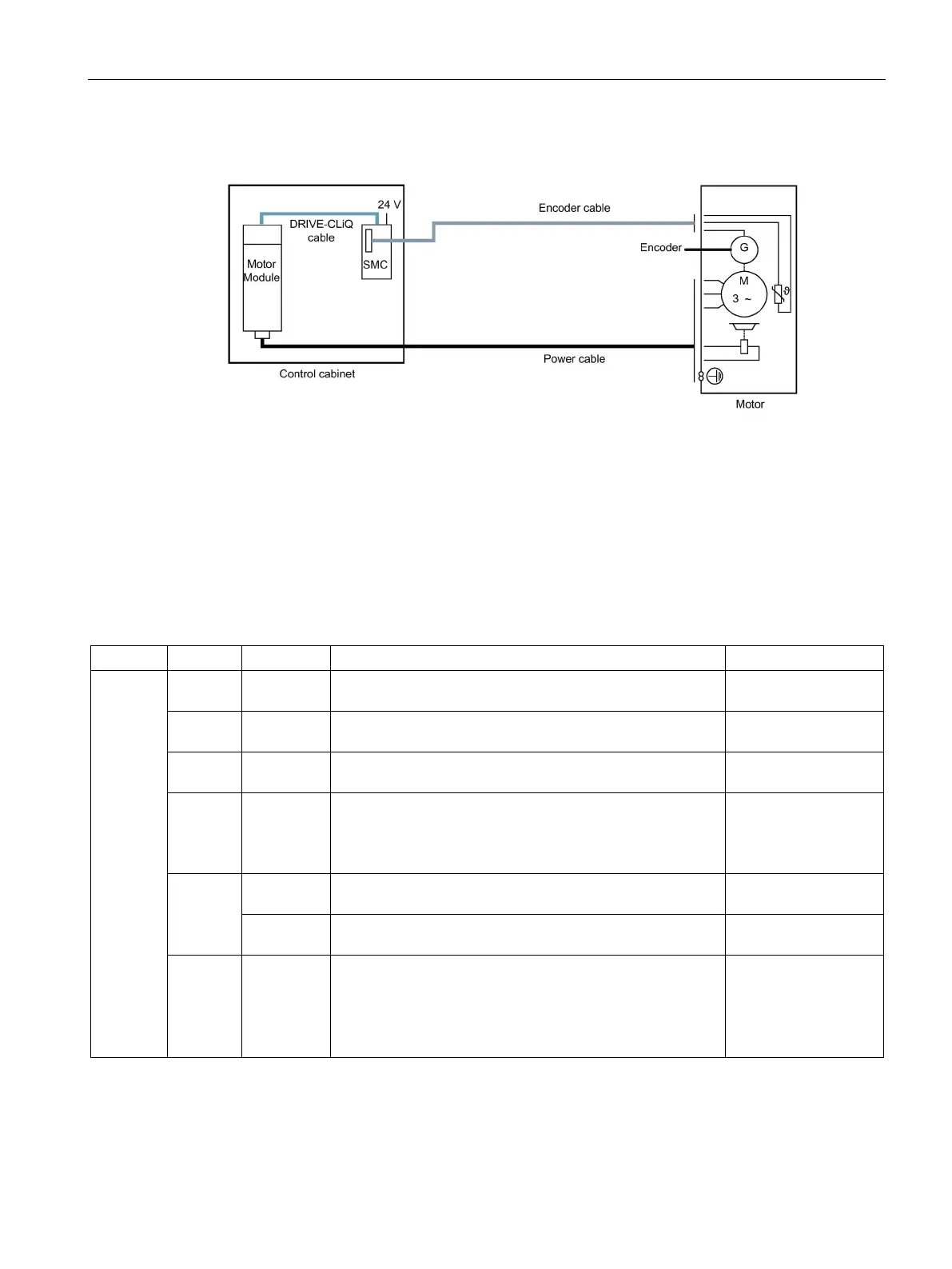
Figure 7-3 Connecting the encoder via a Sensor Module Cabinet-Mounted (SMC)
Meaning of the LED
7.2.4.1
Meaning of the LED on the Sensor Module Cabinet-Mounted SMC10
Table 7- 9 Meaning of the LEDs on the Sensor Module Cabinet-Mounted SMC10
RDY
READY
- Off The electronics power supply is missing or outside the
permissible tolerance range.
–
Green Continuous
The component is ready for operation. Cyclic DRIVE-CLiQ
communication is taking place.
–
Orange Continuous
DRIVE-CLiQ communication is being established. –
Red Continuous
light
This component has at least one fault.
The LED is activated irrespective of whether the
corresponding messages have been reconfigured.
Remove and
acknowledge the fault.
Green/
red
Flashing
Firmware is being downloaded. –
Flashing
Firmware download is complete. The system waits for
Carry out a
Green/
orange
or
Red/
Flashing
light
Component recognition via LED is activated
1)
.
Both options depend on the LED status when component
recognition is activated.
–
1)
Parameters for activating the identification of components via LED are 1.p9210 and 1.p9211 (see DCM List Manual)

 Loading...


