Additional system components
7.5 Terminal Module TM31
SINAMICS DCM DC Converter
Operating Instructions, 12/2018, A5E34763375A
243
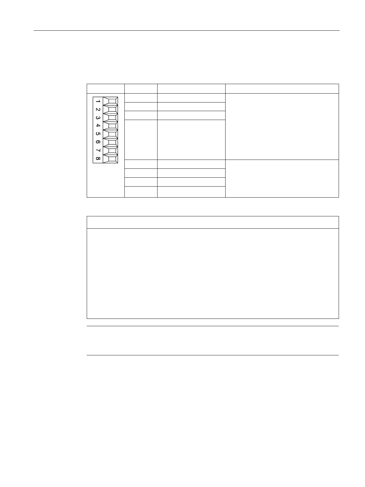
Table 7- 36 X521 terminal strip
The analog inputs can be toggled between
current and voltage input using switches
S5.0 and S5.1
-10 V to +10 V; R
i
= 100 kΩ
Resolution: 11 bits + sign
R
i
= 250 Ω
Resolution: 10 bits + sign
4 AI 1-
:
P10 = 10 V
N10 = -10 V
Current-carrying capacity: max. 3 mA
Sustained short-circuit-proof
8 M
1)
AI: Analog inputs; P10/N10: Auxiliary voltage; M: Ground reference
Damage or malfunctions through impermissible voltage values
If a current exceeding ±35 mA flows through the analog current input, then the component
could be destroyed.
The common mode range must not be violated in order to avoid incorrect analog-digital
conversion results.
• The input voltage may only be in the range between -30 V and +30 V (destruction limit).
• The common mode voltage may only be in the range between -10 V and +10 V
(error limit).
• The back EMF at the auxiliary voltage connections may only be in the range between
-15 V and +15 V.
Note
The power supply for the analog inputs can be taken internally or from an external power
supply unit

 Loading...


