Additional system components
7.5 Terminal Module TM31
SINAMICS DCM DC Converter
242 Operating Instructions, 12/2018, A5E34763375A
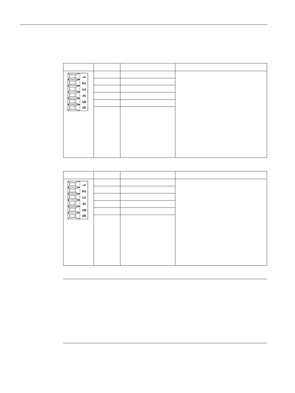
X520, X530 digital inputs
Table 7- 34 Screw terminal X520
Voltage: -3 V to +30 V
Electrical isolation: Yes
Reference potential: M1
Input characteristic acc. to IEC 61131-2,
type 1
Input voltage (including ripple)
"1" signal: 15 V to 30 V
"0" signal: -3 to +5 V
Input current
At 24 V DC: typ. 9 mA
For "1" signal: > 0.5 mA
Input delay:
For "0" → "1": typ. 50 µs/max. 100 µs
For "1" → "0": typ. 130 µs, max. 150 µs
4 DI 3
6 M
Table 7- 35 Screw terminal X530
Voltage: -3 V to +30 V
Electrical isolation: Yes
Reference potential: M2
Input characteristic acc. to IEC 61131-2,
type 1
Input voltage (including ripple)
"1" signal: 15 V to 30 V
"0" signal: -3 to +5 V
Input current
At 24 V DC: typ. 9 mA
For "1" signal: > 0.5 mA
Input delay:
For "0" → "1": typ. 50 µs/max. 100 µs
For "1" → "0": typ. 130 µs, max. 150 µs
6 M
1)
DI: Digital input; M: Electronics ground; M1, M2: Ground reference
Note
Ensuring the function of digital inputs
An open input is interpreted as
"low".
Terminal M1 or M2 must be connected in order that digital inputs (DI) can function.
This is achieved through one of the following measures:
Provide the ground reference of the digital inputs
A jumper to terminal M
: This removes isolation for these digital inputs.

 Loading...


