Tool offsets
8.8 Tool holder kinematics
Job planning
8-40 Programming Manual, 03/2006 Edition, 6FC5398-2BP10-1BA0
8.8 8.8 Tool holder kinematics
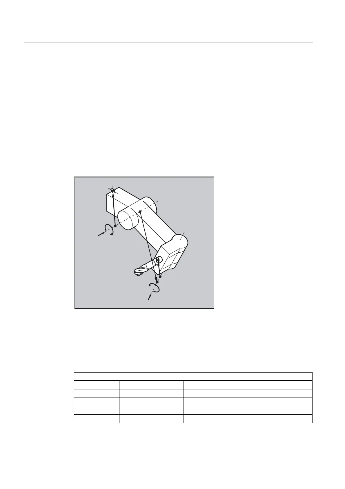
Function
The toolholder kinematics with a maximum of two rotary axes v
1
or v
2
are defined using the
17 system variables $TC_CARR1[m] to $TC_CARR17[m]. The description of the
toolholder consists of:
• the vectoral distance from the first rotary axis of the toolholder I
1
, the vectoral distance
from the first rotary axis to the second rotary axis I
2
, the vectoral distance from the
second rotary axis to the reference point of the tool I
3
.
• the direction vectors of both rotary axes V
1
, V
2
.
• the rotational angles α
1
, α
2
at the two axes. The rotation angles are counted in viewing
direction of the rotary axis vectors, positive, in clockwise direction of rotation.
O
O
O
˞
˞
9
9
For machines with resolved kinematics (both the tool and the part can rotate), the system
variables have been extended with the entries
• $TC_CARR18[m] to $TC_CARR23[m].
Parameters
Function of the system variables for orientable toolholders
Designation x component y component y component
l
1
Offset vector $TC_CARR1[m] $TC_CARR2[m] $TC_CARR3[m]
l
2
offset vector $TC_CARR4[m] $TC_CARR5[m] $TC_CARR6[m]
v
1
rotary axis $TC_CARR7[m] $TC_CARR8[m] $TC_CARR9[m]
v
2
rotary axis $TC_CARR10[m] $TC_CARR11[m] $TC_CARR12[m]

 Loading...


