4 Measuring Cycle for Turning Machines 08.96
4.1.1 L972/L982 Calibrating the tool probe
4.1.1 L972/L982 Calibrating the tool probe
Function and application
The cycle determines the current distances between machine zero point and probe trigger
point with the aid of the calibrating tool and loads them automatically into the MDC area.
Calculations are performed without empirical and average values.
The calibrating tool is located away from the measuring surface by R28 on completion of
calibration.
Tool probes mirror-imaged in the ordinate or abscissa can also be calibrated with this cycle.
Mirror-imaging offers the advantage that probes can be fitted outside the machine work area.
When calibrating, the calibration tool must be positioned in the turret rotated through 180
degrees under PLC control.
Preconditions:
• The side surfaces of the probe cube must be aligned parallel to the machining axes
ordinate and abscissa.
• The calibrating axis must be programmed with G53 and the TO memory number.
• Start position as shown in Fig. 4.1. The measuring cycle calculates the start position
automatically.
Fig. 4.1 Start position when calibrating the tool probe
Calibrating tool
Calibrating tool
a
a
a
a
a
a
a
a
a
a
a
a
a
a
a
a
a
a
a
a
a
a
a
a
a
a
a
a
a
a
a
a
a
a
a
a
a
a
a
a
a
a
a
a
a
a
a
a
a
a
a
a
a
a
a
a
a
a
a
a
a
a
a
a
a
a
a
a
a
a
a
a
a
a
a
a
a
a
a
a
a
a
a
a
a
a
a
a
a
a
a
a
a
a
a
a
a
a
a
a
a
a
a
a
a
a
a
a
a
a
a
a
a
a
a
a
a
a
a
a
a
a
a
a
a
a
a
a
a
a
a
a
a
a
a
a
a
a
a
a
a
a
a
a
a
a
a
a
a
a
a
a
a
a
a
a
a
a
a
a
a
a
a
a
a
a
a
a
a
a
a
a
a
a
a
a
a
a
a
a
a
a
a
a
a
a
a
a
a
a
a
a
a
a
a
a
a
a
a
a
a
a
a
a
a
a
a
a
a
a
a
a
a
a
a
a
a
a
a
a
a
a
a
a
a
a
a
a
a
a
a
a
a
a
a
a
a
a
a
a
a
a
Z
X
M
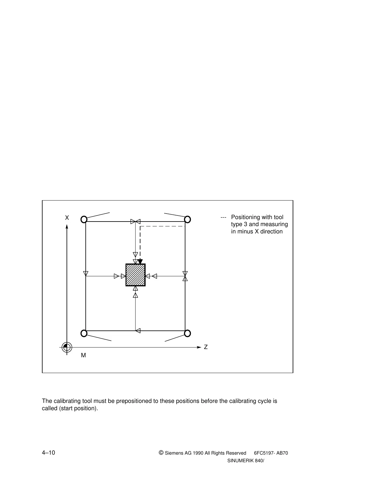
--- Positioning with tool
type 3 and measuring
in minus X direction
The calibrating tool must be prepositioned to these positions before the calibrating cycle is
called (start position).
4–10 ©
Siemens AG 1990 All Rights Reserved 6FC5197- AB70
SINUMERIK 840/850/880 (BN)

 Loading...


