08.96 4 Measuring Cycles for Turning Machines
4.1.2 L972/L982 Measure tool
4.1.2 L972/L982 Measure tool
Function and application
The cycle calculates the new tool length and checks whether the difference, after any neces-
sary compensation by an empirical value, exceeds an amount defined in R36/R37 as compa-
red with the old length. If this is not the case, the new tool length is loaded into the TOA
memory under geometry, otherwise an alarm is triggered.
Compensation is also performed when the deviation exceeds a lower limit specified in R33.The
old tool length is not modified if this is not the case. Such action serves to suppress random
measuring errors.
The tools can also be measured mirror-imaged in the X or Z axis with this cycle (see also
4.1.1).
Averaging is not performed.
On completion of the cycle, the tool tip is now in a position facing the measuring surface by
the amount R28.
Preconditions:
• The tool probe must have been calibrated
• Tool geometry data have been input in the TOA memory with tool nose radius and type.
Example:
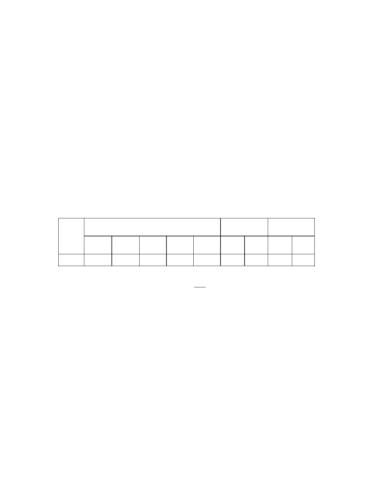
T No. Type Geometry
P0 P1 P2 P3 P4
Wear
P5 P6
Base (add. TO)
P8 P9
D20 3 3 50. 25 1. 0 0 0 0
• The measuring axis must be programmed with G53 (deselect zero offset) and the relevant
tool offset number.
• Start position as shown in Fig. 4.3. The cycle calculates the approach position automa-
tically.
• MD 5007.6 Tool wear is not active
= 0 Tool wear active
The wear memory is cleared by the cycle, the derived offset value is added to
geometry L1 or L2.
= 1 Tool wear not active
The wear is not deleted.
• If tool management is active (MDC 7000.4 = 1, 7000.5 = 1), the calculated difference is
added to the TOA memory the first time the tool is used and the wear value is deleted,
otherwise the calculated difference is added to the wear memory if it is active.
©
Siemens AG 1990 All Rights Reserved 6FC5197- AB70 4–13
SINUMERIK 840/850/880 (BN)

 Loading...


