Functions
2.15 Monitoring Functions
SIPROTEC, 7SD610, Manual
C53000-G1176-C145-6, Release date 02.2011
214
1)
after three unsuccessful restarts, the device is taken out of service.
2)
DOK = „Device OK“ = Break contact of the readiness relay = Life contact
2.15.1.6 Setting Notes
General
The sensitivity of the measured value monitoring can be changed. Experiential values set ex works are ade-
quate in most cases. If particularly high operational asymmetries of the currents and/or voltages are expected,
or if one or more monitoring functions pick up sporadically during normal operation, the sensitivity settings
should be made less sensitve..
The measurement supervision can be switched ON or OFF in address 2901 MEASURE. SUPERV.
Symmetry monitoring
Address 2902 BALANCE U-LIMIT determines the limit voltage (phase-to-phase), above which the voltage
symmetry monitoring is effective. Address 2903 BAL. FACTOR U is the associated balance factor, i.e. the
gradient of the balance characteristic. The indication „Fail U balance“ (no. 167) can be delayed at address
2908 T BAL. U LIMIT. These settings can only be changed using DIGSI at Additional Settings.
Address 2904 BALANCE I LIMIT determines the limit current above which the current symmetry monitoring
is effective. Address 2905 BAL. FACTOR I is the associated balance factor, i.e. the gradient of the balance
characteristic. The indication „Fail I balance“ (no. 163) can be delayed at address 2909 T BAL. I
LIMIT. These settings can only be changed using DIGSI at Additional Settings.
Sum monitoring
Address 2906 ΣI THRESHOLD determines the limit current above which the current sum monitoring is activat-
ed (absolute portion, only relative to I
N
). The relative portion (relative to the maximum phase current) for acti-
vating the current sum monitoring is set at address 2907 ΣI FACTOR. These settings can only be changed
using DIGSI at Additional Settings.
Note
Current sum monitoring can operate properly only when the ground current of the protected line is fed to the
fourth current measuring input (I
4
) of the relay. The I
4
transformer must have been configured as via parameter
I4 transformer (220).
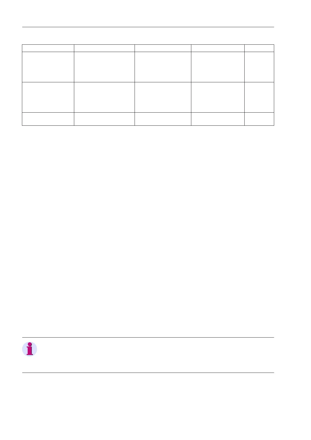
Voltage failure, 1-/2-
phase „Fuse Failure
Monitor“
External (voltage transform-
ers)
Indication
Undervoltage protection
blocked,
Frequency protection
blocked
„VT FuseFail>10s“
(169),
„VT FuseFail“ (170)
As allocated
Voltage failure, 3-phase External (power system or
connection)
Indication
Undervoltage protection
blocked,
Frequency protection
blocked
„Fail U absent“ (168) As allocated
Trip Circuit Monitoring external (trip circuit or
control voltage)
Message „FAIL: Trip cir.“ (6865) as allocated
Supervision Possible Causes Malfunction Response Indication (No.) Device
 Loading...


