Mounting and Commissioning
3.2 Checking Connections
SIPROTEC, 7SD610, Manual
C53000-G1176-C145-6, Release date 02.2011
289
3.2 Checking Connections
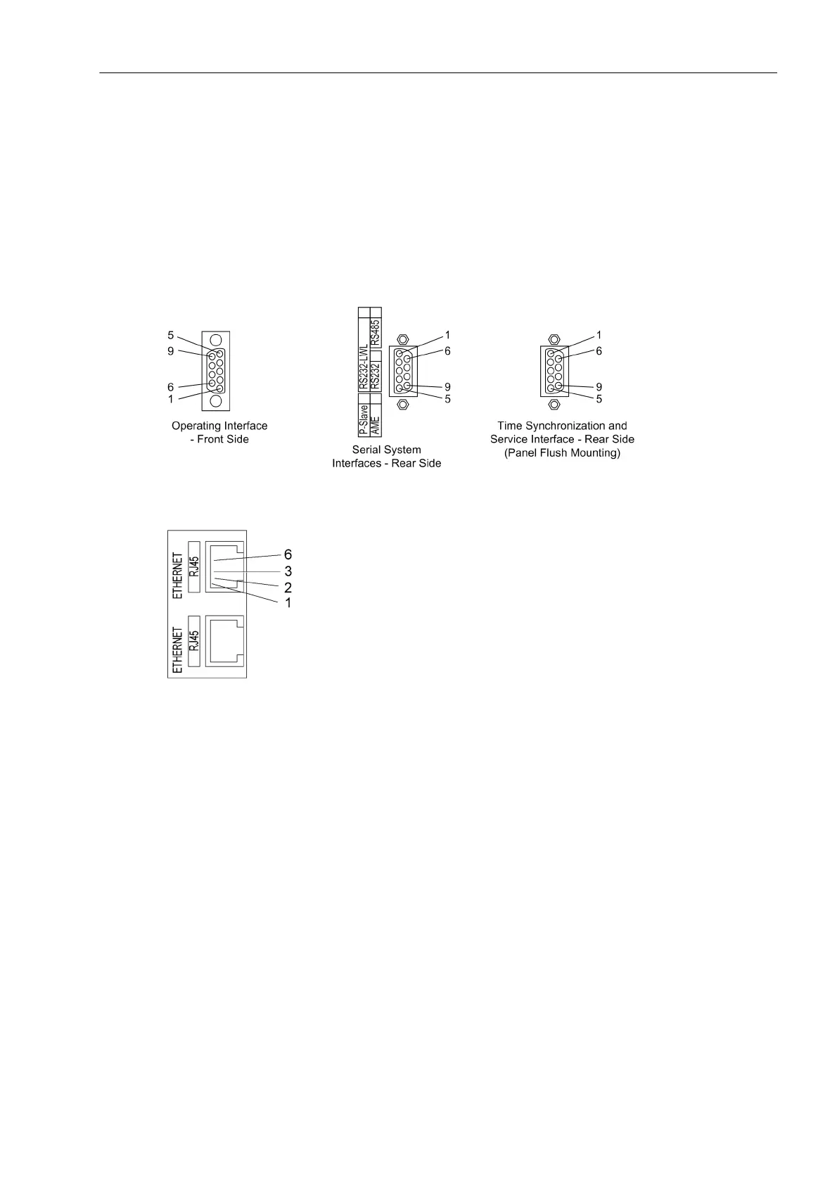
3.2.1 Checking Data Connections of Serial Interfaces
The tables in the following sections list the pin assignments for the different serial interfaces, the time synchro-
nization interface and the Ethernet interface of the device. The position of the connectors is depicted in the fol-
lowing figures.
Figure 3-14 9-pin D-subminiature female connectors
Figure 3-15 Ethernet connector
Operator Interface
When the recommended communication cable is used, correct connection between the SIPROTEC 4 device
and the PC is automatically ensured. See the Appendix A.1 for an ordering description of the cable.
Service interface
Check the data connection if the service interface is used to communicate with the device via hard wiring or
modem.
 Loading...


