Technical Data
4.3 Inverse-Time Overcurrent Protection 51(N)
SIPROTEC, 7SJ62/64, Manual
C53000-G1140-C207-2, Release date 01.2008
481
4.3 Inverse-Time Overcurrent Protection 51(N)
Operating Modes
Measuring Technique
Setting Ranges / Increments
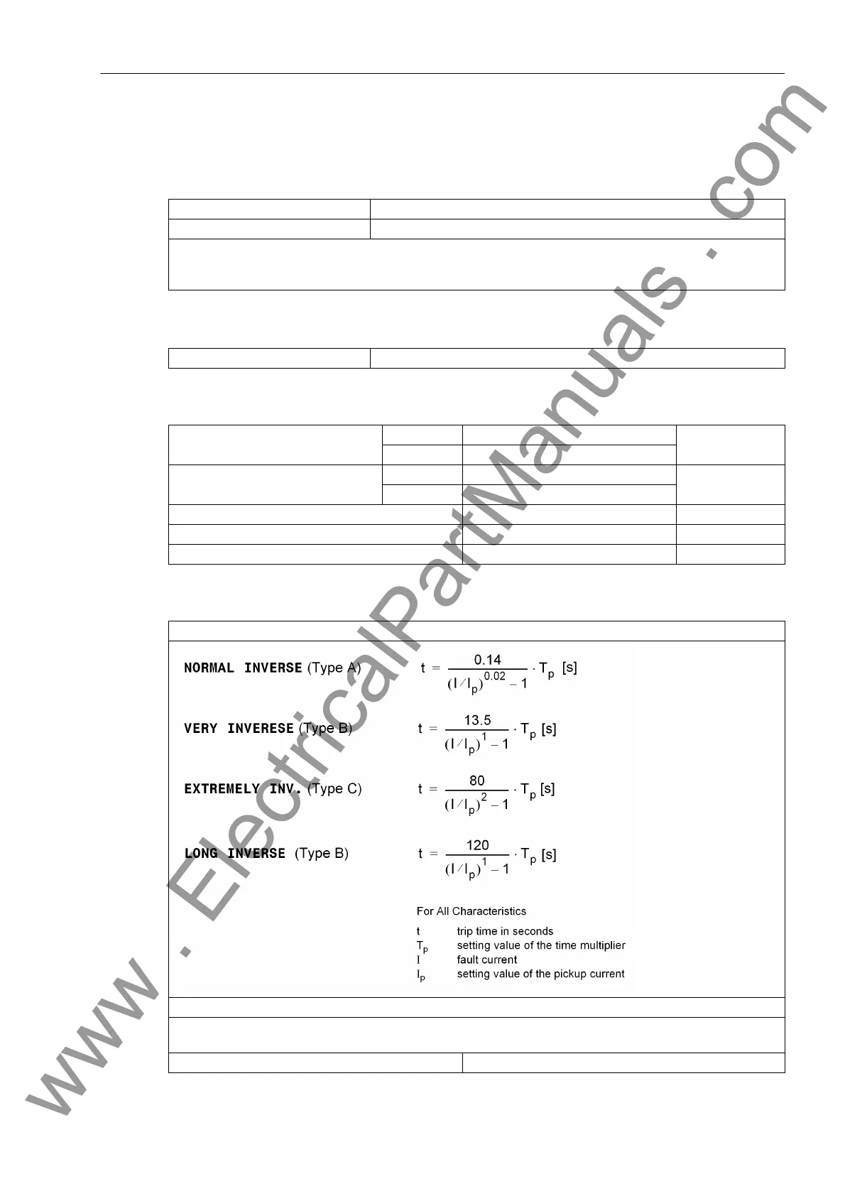
Trip Time Curves acc. to IEC
Three-phase Standard
Two-phase Phases A and C
voltage-independent,
voltage-controlled,
voltage-dependent
All elements First harmonic, rms value (true rms)
Pickup current 51 (phases) for I
Nom
= 1 A 0.10 A to 4.00 A Increments 0.01 A
for I
Nom
= 5 A 0.50 A to 20.00 A
Pickup current 51N
(ground)
for I
Nom
= 1 A 0.05 A to 4.00 A Increments 0.01 A
for I
Nom
= 5 A 0.25 A to 20.00 A
Time multiplier T for 51, 51N for IEC curves 0.05 s to 3.20 s or ∞ (disabled) Increments 0.01 s
Time multiplier T for 51, 51N for ANSI curves 0.50 s to 15.00 s or ∞ (disabled) Increments 0.01 s
Undervoltage threshold 51V V< for release of 51 10.0 V to 125.0 V Increments 0.1V
Acc. to IEC 60255-3 or BS 142, Section 3.5.2 (see also Figure 4-1 and 4-2)
The tripping times for I/I
p
≥ 20 are identical with those for I/I
p
= 20.
For zero-sequence current read 3I0p instead of I
p
and T
3I0p
instead of T
p
;
for ground fault read I
Ep
instead of I
p
and T
IEp
instead of T
p
Pickup Threshold approx. 1.10 · I
p
www . ElectricalPartManuals . com
 Loading...


