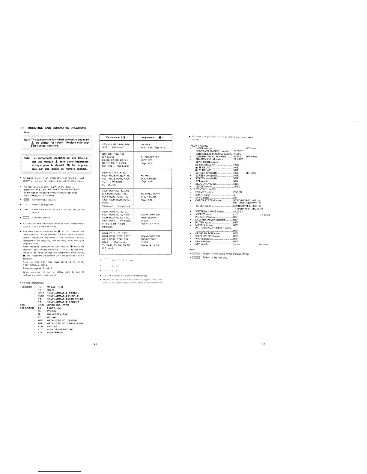
5-3. MOUNTING AND SCHEMATIC DIAGRAMS
Note:
Note: The components identified by shading and mark
,& are critical for safety. Replace only with
part number specified.
Note: Les composants identifies par une trame et
par une marque ,& sont d'une importance
critique pour la securite. Ne les remplacer
aue par des pieces de numero specifie.
• All capacitors are In µF unless otherwise noted. p · µµF
50 WV or less are not 1nd1cated except for electrolyt1cs.
• All resistor are in ohms, 1/2W on the C board,
1 / 1 OW on the BT, DC, HY, and HZ boards and 1 /4W
on the rest of the boards unless otherwise specified.
kn = 1 ooon, Mn = 1 oookn
•
~
· nonflammable resistor.
• ti
• +
internal component.
direct connection to points marked + on the
chassis
• C=:J : panel des1gnat1on.
• All variable and ad1ustable resistors have characteristic
curve 8, unless otherw1se noted.
• The components 1dent1f1ed by B In this manual have
been carefully factory-selected for each set In order to
satisfy regulations regarding X-ray radiation. Should
replacement be required, replace only with the value
originally used.
When replacing components 1dent1f1ed by ~- make the
necessary adjustments 1nd1cated. If results do not meet
the spec1f1ed value, change the component 1dent1f1ed by
B and repeat the adJustment until the specified value Is
achieved.
Refer to R52, R53, R67, R68, R124, R126, R222,
R227, R228 and R239.
Adjust on page 4-13 -4-18.
When replacing the part In below table, be sure to
perform the related adjustment.
Reference information
RESISTOR
COIL
RN
RC
METAL FILM
SOLID
FPRD NONFLAMMABLE CARBON
FUSE NONFLAMMABLE FUSIBLE
RS NONFLAMMABLE WIREWOUND
RB NONFLAMMABLE CEMENT
LF-8L MICRO INDUCTOR
CAPACITOR: TA
TANTALUM
PS STYROL
PP POLYPROPYLENE
PT MYLAR
MPS METALIZED POL YEST ER
MPP METALIZED POLYPROPYLENE
ALB BIPOLAR
ALT HIGH TEMPERATURE
AIR HIGH RIPPLE
5-5
Part replaced ( .iii )
Adjustment (el
C59, IC3, R67, R68, R78,
B+MAX
RV2 ... (GA board) (R67, R68)
Page 4-13,
013, 014, R52, R53
(GA board)
B+ PROTECTER
D5, 0-6, D7, DB, 03, 04,
(R52, R53)
Q~R4,R~ R1~ R2~
Page 4-13.
R21, R22 ... (GB board)
D216, IC1, IC4, R123,
R124, R125, R126, R136, HV REG
R137, R138, R203, R204,
(R124, R126)
RV1 ... (PA board)
Page 4-18,
DCT BLOCK
D205,D207,D214,D215
IC2, R201, R202, R213,
HV HOLD DOWN
R214, R225, R226, R227,
(R227, R228)
R228, R229, R230, R243,
Page 4-16.
R245 ....
(PA board)
DCT BLOCK
D205, D206, D215, IC2,
R201, R202, R213, R214, BEAM CURRENT
R220, R221, R222, R223,
PROTECTOR-1
R224, R242 ... (PA board) (R222)
T1 (FBT), R1, R2, R5 ..
Page 4-13 - 4-16
(PB board)
D204, D216, IC3, R203,
R204, R231, R232, R237,
BEAM CURRENT
R238, R239, R240, R241, PROTECTOR·2
R247
... (PA board)
(R239)
T1 (FBT), R3, R4, R5, R6.
Page 4-14 - 4-15
(PB board)
9 - - - 8 !)cJC.
• Circled numbers Dre waveform references.
• WaveforrT1s are tdketi w1H1 a color-bar Signal input and
with a 75~? terminator connected to an open terminal
• Switches and controls are set as follows unless otherw,se
noted.
FRONT PANEL
INPUT selector ................................ I
HX board
CONTRAST MANUAL switch ...... PRESET
BRIGHTNESS MANUAL switch ... PRESET
l
CHROMA MANUAL switch .......... PRESET
HW board
PHASE MANUAL switch ............... PRASET
SCAN MODE switch
J
@ UNDER SCAN .......................... NOR
!ll H. DELAY ................................. NOR
8 V. DELAY ................................. NOR
l
SCREEN switch (R) ........................ NOR
HA board
SCREEN switch (G) ........................ NOR
SCREEN switch (B) ........................ NOR
APT switch ...................................... NOR
BLUE ONL Yswitch ........................ NOR
MODE selector ................................ AUTO
j
SUB CONTROL PANEL
FORMAT button ............................. CODED
INPUT button .................................. A
SYNC button ................................... INT
COLOR SYSTEM button ................ NTSC (BVM-1311/1911)
PAL (BVM-141 IP/201 lP)
YC SEP button ................................. COMB (BVM-1311/1911)
TRAP (BVM-141 lP/201 lP)
Note:
WHITE BALANCE button ............. D65/D93
ASPECT button ............................... 4 : 3
PIC SETUP button ........................... OFF
SAD/VITC/MARKERbutton .......... OFF
FILTER button ................................ OFF
MA TRJX button __ OFF
PAL S/SECAM F/COMB S button .
............................... , ..... , ................... OFF
CROSS HATCH button ................... OFF
SPLIT SCREEN button ................... OFF
WHITE button ................................. OFF
ORA Y button ................................... OFF
AFC switch ..................................... 2m sec
: Pattern from the side which enables seeing.
: Pattern of the rear siae.
HY board
DA board
5-6
 Loading...