4-5. SETUP ADJUSTMENT IN CASE OF PICTURE
TUBE REPLACEMENT
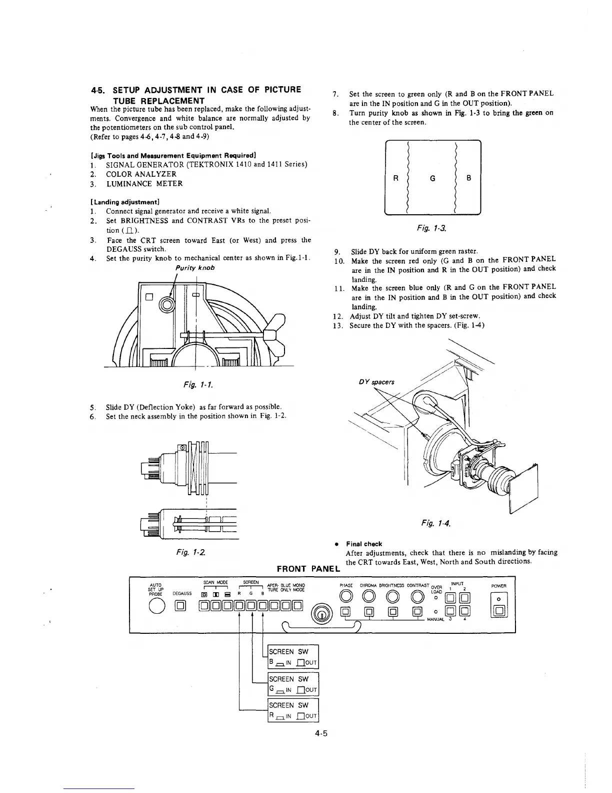
When the picture tube has been replaced, make the following adjust-
ments. Convergence and white balance are normally adjusted by
the potentiometers on the sub control panel.
(Refer to pages 4-6, 4-7, 4-8 and 4-9)
[Jigs Tools and Measurement Equipment Required]
l. SIGNAL GENERATOR (TEKTRONIX 1410 and 1411 Series)
2. COLOR ANALYZER
3. LUMINANCE METER
[ Landing adjustment]
1. Connect signal generator and receive a white signal.
2. Set BRIGHTNESS and CONTRAST VRs to the preset posi-
tion (ll).
3. Face the CRT screen toward East (or West) and press the
DEGAUSS switch.
4. Set the purity knob to mechanical center as shown in Fig.1-1.
Purity knob
Fig. 1-1.
5. Slide DY (Deflection Yoke) as far forward as possible.
6. Set the neck assembly in the position shown in Fig. 1-2.
Fig. 1-2.
7. Set the screen to green only (R and B on the FRONT PANEL
are in the IN position and G in the OUT position).
8. Turn purity knob as shown in Fig. 1-3 to bring the green on
the center of the screen.
9.
10.
11.
12.
13.
)
)
R
G
B
Fig. 1-3.
Slide DY back for uniform green raster.
Make the screen red only (G and B on the FRONT PANEL
are in the IN position and R in the OUT position) and check
landing.
Make the screen blue only (R and G on the FRONT PANEL
are in the IN position and B in the OUT position) and check
landing.
Adjust DY tilt and tighten DY set-screw.
Secure the DY with the spacers. (Fig. 1-4)
Fig. 1-4.
• Final check
FRONT PANEL
After adjustments, check that there is no mislanding by facing
the CRT towards East, West, North and South directions.
AUTO
SET UP
PROBE
0
DEGAUSS
SCAN MOOE SCREEN APER-BLUE MONO
r-.-----i r-.-----i TURE ONL 'f MODE
[§1 [1J i!! R G B
[g[g[g[g[g[g[g[g[g
SCREEN SW
B .=.1N Qour
SCREEN SW
G .=.IN Qour
SCREEN SW
.___--I
R .=.IN QOUT
4-5
PHASE CHROMA BRIGHTNESS CONTRAST OVER
1
INPUT
2
0 0 0 0 L~AD[g[g
POWER
~
~
~
ij W:uAL l9l
~
 Loading...