>-
..J
co
::;
LJ.J
CJ)
i
0
"
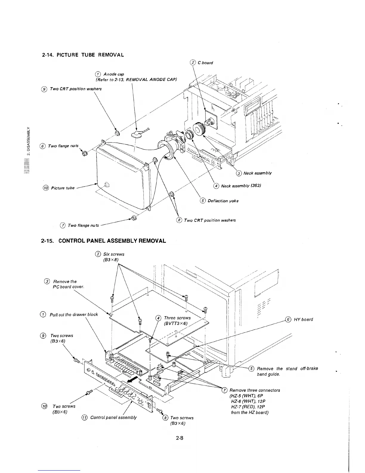
2-14. PICTURE TUBE REMOVAL
@ Cboard
(D Anode cap
(Refer to 2-13. REMOVAL ANODE CAP)
® Two CRT position washers
\
\/6/
' / I
@ Twofl,,,geouo~~ /
I
'"~~/~~
@ Picture tube
l
··-.,~
~' /
~
0 Two flange nuts ________ ,
2-15. CONTROL PANEL ASSEMBLY REMOVAL
@ Remove the
PC board cover.
0 Six screws
(83X8)
(D Pull out the drawer block
® Twoscrews
@
@ Neck assembly (362)
@ Deflection yoke
@ Two CRT position washers
6 HY board
5 Remove the stand off-brake
2-8
band guide.
7 Remove three connectors
(HZ-5 (WHT), 6P
HZ-6 (WHT), 12P
HZ-7(RED), 12P
from the HZ board)
 Loading...