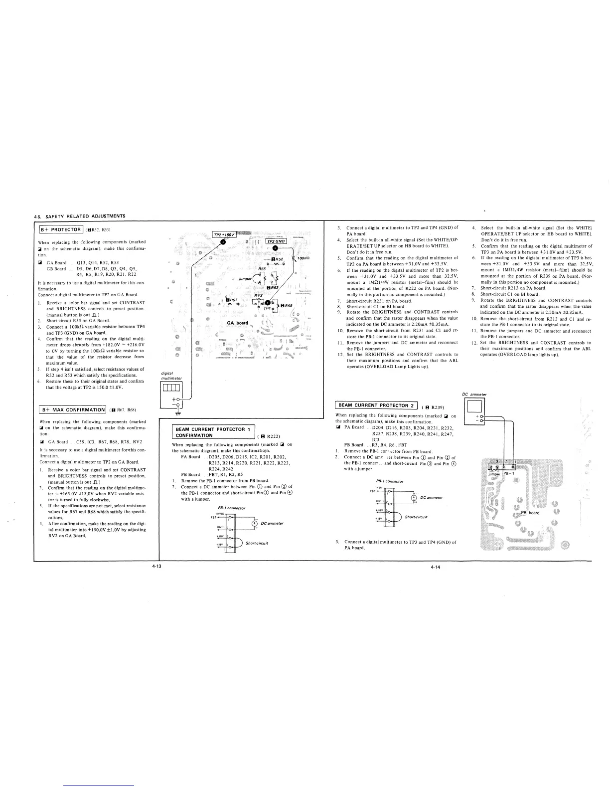
4-6. SAFETY RELATED ADJUSTMENTS
js+ PROTECTOR I (BR5~. R53l
When replacing the following components (marked
[;ii on the schematic diagram), make this confirma-
tion.
[;ii GA Board
GB Board
Ql3, Ql4, R52, R53
D5, D6, D7, D8, Q3, Q4, QS,
R4, RS, R!9, R20, R21, R22
It is necessary to use a digital multimeter for this con-
firmation.
Connect a digital multimeter to TP2 on GA Board.
I. Receive a color bar signal and set CONTRAST
and BRIGHTNESS controls to preset position.
(manual button is out .Il.)
1
Short-circuit RSS on GA Board.
3. Connect a 100ki1 variable resistor between TP4
and TP3 (GND) on GA board.
4. Confirm that the reading on the digital multi-
meter drops abruptly from +182.0V ~ +216.0V
to 0V by turning the I 00ki1 variable resistor so
that the value of the resistor decrease from
maximum value.
5. If step 4 isn't satisfied, select resistance values of
R52 and R53 which satisfy the specifications.
6. Restore these to their original states and confirm
that the voltage at TP2 is 150.0 ±J.0V.
B+ MAX CONFIRMATION I (B Rn7. Rn8)
When replacing the following components (marked
I.ii on the schematic diagram), make this confirma-
tion.
I.iii GA Board .. C59, JC3, R67, R68, R78, RV2
It is necessary to use a digital multimeter for•this con-
firmation.
Connect a digitai multimeter to TP2 on GA Board.
I. Receive a color bar signal and set CONTRAST
and BRIGHTNESS controls to preset position.
(manual button is out .Il.)
2. Confirm that the reading on the digital multime-
ter is +165.0V ±13.0V when RV2 variable resis-
tor is turned to fully clockwise.
3. If the specifications are not met, select resistance
values for R67 and R68 which satisfy the specifi-
cations.
4. After confirmation, make the reading on the digi-
tal multimeter into+ I 50.0V ±1.0V by adjusting
RV2 on GA Board.
digital
multimeter
R55.
jumper~--~
1111~~
4-13
BEAM CURRENT PROTECTOR 1
CONFIRMATION
( B R222)
When replacing the following components (marked [;ii on
the schematic diagram), make this confirmatiojn.
PA Board .. D205, D206, D215, IC2, R201, R202,
R213,R214,R220,R221,R222,R223,
R224, R242
PB Board .. FBT, RI, R2, RS
I. Remove the PB-I connector from PB board.
2. Connect a DC ammeter between Pin CD and Pin a) of
the PB-I connector and short-circuit Pin G) and Pin ©
with a jumper.
PB-1 connector
IHVIII
FBT--l+--0.-+!----~
DC ammeter
Short-circuit
3. Connect a digital multimeter to TP2 and TP4 (GND) of
PA board.
4. Select the built-in all-white signal (Set the WHITE/OP-
ERATE/SET UP selector on HB board to WHITE).
Don't do it in free run.
5. Confirm that the reading on the digital multimeter of
TP2 on PA board is between +31.0V and +33.SV.
6. If the reading on the digital multimeter of TP2 is bet-
ween +31.0V and +33.SV and more than 32.SV,
mount a !Mi11/4W resistor (metal-film) should be
mounted at the portion of R222 on PA board. (Nor-
mally in this portion no component is mounted.)
7. Short-circuit R231 on PA board.
8. Short-circuit Cl on Bl board.
9. Rotate the BRIGHTNESS and CONTRAST controls
and confirm that the raster disappears when the value
indicated on the DC ammeter is 2.20mA ±0.35mA.
I 0. Remove the short-circuit from R23 l and CI and re-
store the PB-I connector to its original state.
I I. Remove the jumpers and DC ammeter and reconnect
the PB-I connector.
12. Set the BRIGHTNESS and CONTRAST controls to
their maximum positions and confirm that the ABL
operates (OVERLOAD Lamp Lights up).
BEAM CURRENT PROTECTOR 2
( B R239)
When replacing the following components (marked ~ on
the schematic diagram), make this confirmation.
~
PA Board .. D204, D216, R203, R204, R231, R232,
R237, R238, R239, R240, R241, R247,
IC3
PB Board .. R3, R4, R6, FBT
I. Remove the PB-I con· ector from PB board.
2. Connect a DC amr ,er between Pin CD and Pin @ of
the PB-I connect-.; and short-circuit Pin G) and Pin ©
with a jumper
PB-1 connector
IHVII I
FBT---tt-,U.-tt---~
DC ammeter
Short-circuit
3. Connect a digital multimeter to TP3 and TP4 (GND) of
PA board.
4-14
4. Select the built-in all-white signal (Set the WHITE/
OPERATE/SET UP selector on HB board to WHITE).
Don't do it in free run.
5. Confirm that the reading on the digital multimeter of
TP3 on PA board is between +31.0V and +33.SV.
6. If the reading on the digiatal multimeter of TP3 is bet-
ween +31.0V and +33.SV and more than 32.SV,
mount a !Mi11/4W resistor (metal-film) should be
mounted at the portion of R239 on PA board. (Nor-
mally in this portion no component is mounted.)
7. Short-circuit R213 on PA board.
8. Short-circuit Cl on BI board.
9. Rotate the BRIGHTNESS and CONTRAST controls
and confirm that the raster disappears when the value
indicated on the DC ammeter is 2.20mA ±0.35mA.
1 0. Remove the short-circuit from R2 I 3 and Cl and re-
store the PB-1 connector to its original state.
11. Remove the jumpers and DC ammeter and reconnect
the PB-1 connector.
12. Set the BRIGHTNESS and CONTRAST controls to
their maximum positions and confirm that the ABL
operates (OVERLOAD lamp lights up).
DC ammeter
9-
 Loading...