3-12. POWER SUPPLY CIRCUIT (GA, GB BOARDS)
3-12-1. AC Power Supply, Rectifier Circuit
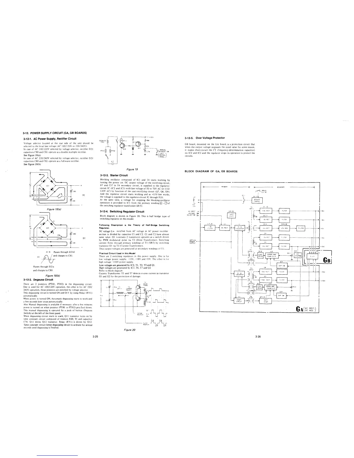
Voltage selector located at the rear side of the unit should be
selected to the local line voltage (AC I 00/l 20V or 220/240V)
In case of AC 100/120V selected by voltage selector, rectifier D21
capacitors C80 and C81 operate as a double multiple rectifier.
See Figure l 8(a).
In case of AC 220/240V selected by voltage selector, rectifier D21
capacitors C80 and CS I operate as a full-wave rectifier.
See Figure 18(b).
AC
IN
',-------'--,---- +
Figure 18(a)
r
I
AC
IN
D21
b
J
l+ CBO
ON~
T
-ti
+
I CBI
I
AC 1N Passes through D2ld
AC ~d charges to CS!.
Passes through D2 I a
and charges to C80.
Figure 18(b)
3-12-2. Degauss Circuit
DC
+
DC
There are 2 posistors (PTHJ, PTH2) in the degaussing circuit.
One is used for AC I 00/120V operation. the other is for AC 220/
240V operation, these posistors are switched by voltage selector.
This degaussing circuit is turned ON and OF!- by using Relay (RY 1)
automatically.
When power is turned ON, Automatic degaussing starts to work and
a few seconds later stops automatically.
Also Manual degaussing is available if necessary after a few minutes
power is turned on when posistor (PTHl or PTH2) gets cool down.
This manual degaussing is operated by a push of button (Degauss
Switch) at the left of the front panel.
When degaussing circuit starts to WQrk, QI I transistor turns on by
time constant circuit composed of resistors R88, 91 and capacitor
C74. Oil drives Q12 transistor. Relay (RY]) is driven by Ql2.
Time constant circuit keeps degaussing circuit to activate for several
seconds until degaussing is finished.
3-25
r-------.------.---- + 12 V
COIL
DEGAUS~~~-
PTHI
1
, 'PTH2 l
JRS~
~
MANUAL
I
C 74 /DEGAUSS SW
AC
0
Figure 19
3-12-3. Starter Circuit
lfcoLJi;oL)
\ PANEL
Blocbng oscillator composed of IC! and T4 starts working by
turning the power on. DC output voltage of the rectifying-circuit,
D7 and C57 in T4 secondary circuit, is supplied to the regulator-
circuit IC (IC2 and IC3) with line voltage of 50 to 70V AC (at 110/
120V AC) by function of the start-rectifying circuit (07, 08, Q9).
And the regulator circuit starts working and as + I SV-line works,
the voltage is supplied to the regulator-circuit IC through D20.
At the same time, a voltage for stopping the blocking-oscillator
operation is provided to !Cl from the primary winding@-G)of
the switching regulator transformer SRT2.
3-12-4. Switching Regulator Circuit
Block diagram is shown in Figure 20. This is half bridge type of
switching regulator in this model.
Following Description is the Theory of Half·Bridge Switching
Regulator.
DC voltage [1N rectified from AC voltage in AC power rectifier
section is divided by capacitor Cl and C2. Cl and C2 have almost
same value. QI (contains 2 transistors) operates as a switch driven
by PWM modulated pulse via T2 (Drive Transformer). Switching
current flows through primary windings of Tl ( SRT) by switching
transistor QI via T3 (Current Transformer).
Thus output voltages arc generated at secondary windings of T 1
Practical Circuit Used in this Model
There are 2 switching regulators in this power supply. One is for
low voltage power supply. •15V, •18V and +5V. The other is fur
high voltage 'I SOY power supply.
Low voltages are generated by IC2, Tl, T2, T3 and Ql.
High voltages are generated by IC3, T6, T7 and Q2
Refer to block diagram
Current Transformer T3 and T7 detects e:xcess current in transistor
QI and Q2 for the protection of damage.
Figure 20
3-12-5. Over Voltage Protector
GB board, mounted on the GA board, is a protection circuit that
when the output voltage surpasses the rated value for some reason,
it makes short-circuit the CT (frequency-determination capacitor)
on IC2 and IC3 and the regulator stops its operation to protect the
circuits.
BLOCK DIAGRAM OF GA, GB BOARDS
PRIMARY
~0-, MANUAL
D.V SW
(
D G
1
~-------1---
TI
011 ,12
DEGAUSS
CONTROL
SRT I
AC INPUT <>-
VOLTAGE rt'f-
SELECT SW l_h 0-----------i
022, 26
~
DI , 10
t 18v' RECT
02, 11
-131, REC
SEC0NDAR'r'
FILTER
1-----------~ +18V
FILTER
-18\1
L 17, 18
j D2
D5,5 D18,018
OPTION
POWER
SUPPLY
DC-AC
(ONVfRTfR
[ ~---8--B----'-....l.-----'1 t5V
1--------~-Ll-.-). - 15V
Goj
15
CZ SRT 2
JC AC
~
::,
CONVERTER ..J
1------1----+--4--l--<.I, - 150\1
+---'---3 I
1---..----1----J---h-tJ + 150V
t+------..:RV2
I
L
1(1 T4
KICK
START ! {:
(IR(,Ji,. I \_
---
G
~(AC RECT,)
J.-1 DC REG
3-26
 Loading...