3-7. BEAM CONTROL CIRCUIT (Bl, BK BOARDS)
(Same as Green and Blue)
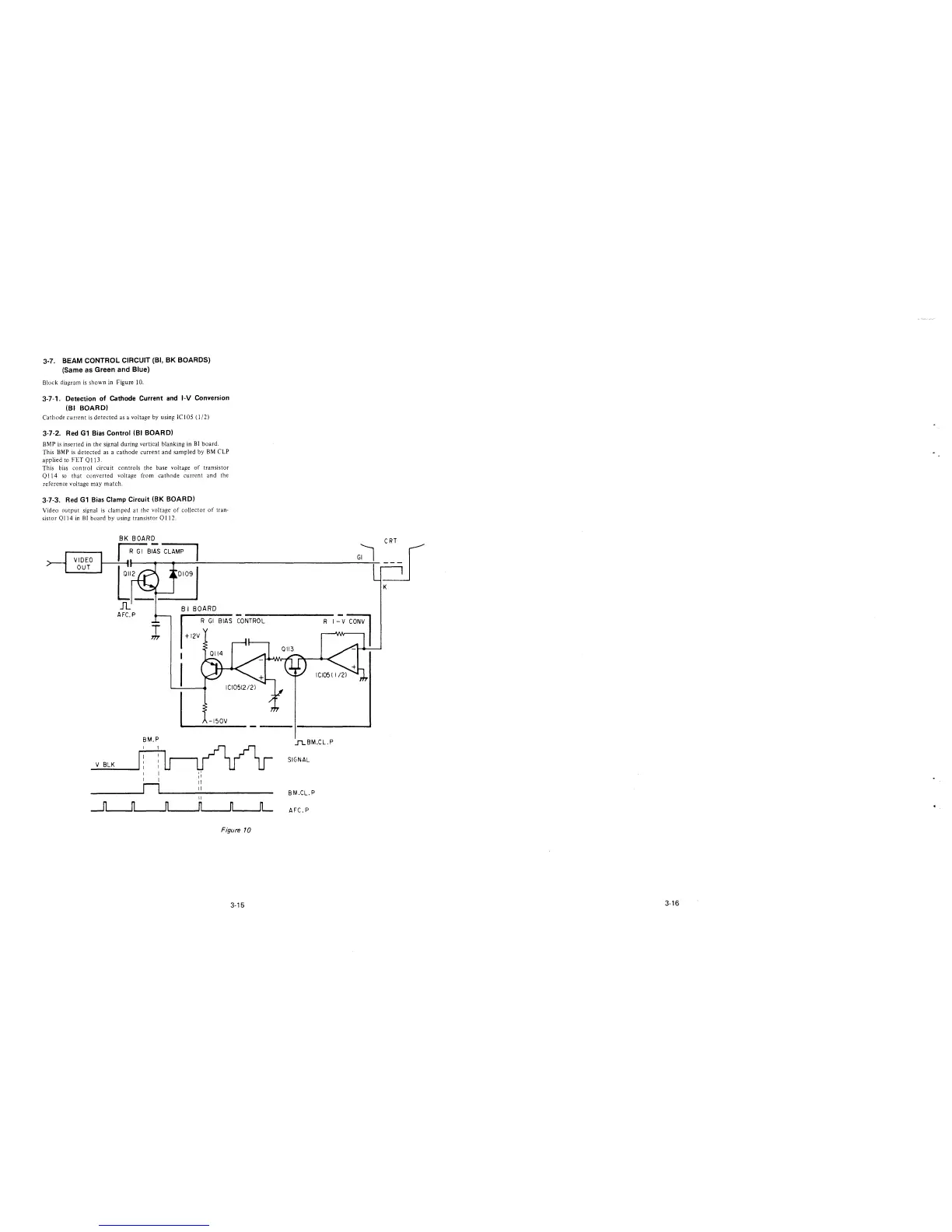
Block diagram is shown in figure 10.
3-7-1. Detection of Cathode Current and 1-V Conversion
(Bl BOARD)
Cathode current is detected as a voltage by using ICIOS (l/2)
3-7-2. Red Gl Bias Control (Bl BOARD)
BMP is inserted in the signal during vertical blanking in BI board.
This BMP is detected as a cathode current and sampled by BM CLP
applied to FET QI I 3.
This bias control circuit controls the base voltage of transistor
Ql 14 so that converted voltage from cathode current and the
reference voltage may match.
3-7-3. Red Gl Bias Clamp Circuit (BK BOARD)
Video output signal is clamped at the voltage of collector of tran·
sistor Ql 14 in Bl board by using transistor Ql 12.
BI BOARD
R GI BIAS CONTROL
I
+12v
I
I
~-
BM.P
V BLK
I
I
I
,,
I
11
n
ii
ii
II
_n ___
n n n
n
L
Figure 10
3-15
R
..I1..BM.CL.P
SIGNAL
BM.CL.P
AFC.P
3-16
 Loading...