1-3-4. Switches inside the Cabinet
To access to the switches on the boards inside the cabinet, see Section 2.
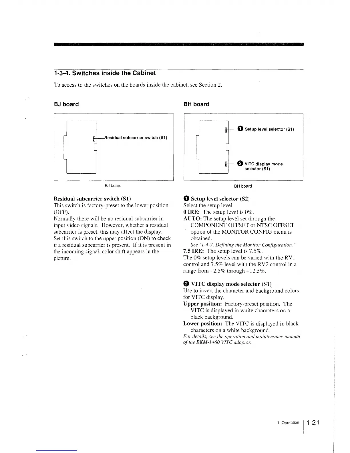
BJ board
esidual subcarrier switch (S1)
BJ board
Residual subcarrier switch (S1)
This switch is factory-preset to the lower position
(OFF).
Normally there will be no residual subcarrier in
input video signals. However, whether a residual
subcarrier is preset, this may affect the display.
Set this switch to the upper position (ON) to check
if a residual subcarrier is present. If it is present in
the incoming signal, color shift appears in the
picture.
BH board
0 Setup level selector (S1)
@ VITC display mode
selector (S1)
BH board
0 Setup level selector (S2)
Select the setup level.
0 iRE: The setup level is 0%.
AUTO: The setup level set through the
COMPONENT OFFSET or NTSC OFFSET
option of the MONITOR CONFIG menu is
obtained.
See "1-4-7. Defining the Monitor Co,{figuration."
7.5 IRE: The setup level is 7.5%.
The 0% setup levels can be varied with the RV]
control and 7.5% level with the RV2 control in a
range from -2.5% through+ 12.5%.
8 VITC display mode selector (S1)
Use to invert the character and background colors
for VITC display.
Upper position: Factory-preset position. The
VITC is displayed in white characters on a
black background.
Lower position: The VITC is displayed in black
characters on a white background.
For details, see the operation and maintenance manual
of the BKM-1460 VJTC adaptor.
1. Operation 11-21
 Loading...