5-24
5. Bright Adjustment (PD-98 board)
Set the level of the VIDEO signal for driving the LCD to the specified
value. If deviated, the screen image will be blackish or saturated
(whitish).
Mode VTR playback
Signal Alignment tape:
For audio operation check
(XH5-3 (NTSC))
(XH5-3P (PAL))
Measurement Point Pin 2 of CN5501 (VG)
External trigger : Pin 4 of CN5501
(PANEL COM)
Measuring Instrument Oscilloscope
Adjustment Page D
Adjustment Address 6C
Specified Value A = 1.40 ± 0.05V (NTSC)
A = 1.40 ± 0.05V (PAL)
Connections:
Connect Pin 9 (X-TEST) and Pin 5 (GND) of CN5501 with a
jumper wire.
Adjusting method:
1) Select page: 0, address: 01, and set data: 01.
2) Input the following data to page: D, address: 82 and 83.
Note: Press the PAUSE button of the adjustment remote commander
each time to set the data.
3) Select page: D, address: 6C, change the data and set the voltage
(A) between the pedestal and white to the specified value. (The
data of address: 6C should be “41” to “BF”.)
4) Press the PAUSE button of the adjusting remote commander.
5) Input the following data to page: D, address: 82 and 83.
Note: Press the PAUSE button of the adjustment remote commander
each time to set the data.
6) Select page: 0, address: 01, and set data: 00. 7) Perform
“Contrast Adjustment”.
7) Perform “Contrast Adjustment”.
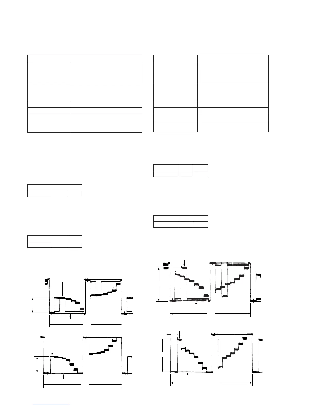
For NTSC model
For PAL model
Fig. 5-1-18
Address
Data
82
00
83
00
Address
Data
82
20
83
20
White
Pedestal
A
2H
White
Pedestal
A
2H
6. Contrast Adjustment (PD-98 board)
Set the level of the VIDEO signal for driving the LCD to the specified
value. If deviated, the screen image will be blackish or saturated
(whitish).
Mode VTR playback
Signal Alignment tape:
For audio operation check
(XH5-3 (NTSC))
(XH5-3P (PAL))
Measurement Point Pin 2 of CN5501 (VG)
External trigger : Pin 4 of CN5501
(PANEL COM)
Measuring Instrument Oscilloscope
Adjustment Page D
Adjustment Address 62
Specified Value A = 2.54 ± 0.07V (NTSC)
A = 2.54 ± 0.07V (PAL)
Adjusting method:
1) Select page: 0, address: 01, and set data: 01.
2) Input the following data to page: D, address: 82 and 83.
Note: Press the PAUSE button of the adjustment remote commander
each time to set the data.
3) Select page: D, address: 62, change the data and set the voltage
(A) between the 0 IRE (pedestal) and 100 IRE to the specified
value.
4) Press the PAUSE button of the adjusting remote commander.
5) Input the following data to page: D, address: 82 and 83.
Note: Press the PAUSE button of the adjustment remote commander
each time to set the data.
6) Select page: 0, address: 01, and set data: 00.
7) Check that the specified value of “Bright Adjustment” is
satisfied, if not perform “Bright Adjustment”.
For NTSC model
For PAL model
Fig. 5-1-19
Address
Data
82
00
83
00
Address
Data
82
20
83
20
A
2H
100 IRE
0 IRE
A
2H
100 IRE
0 IRE
 Loading...