5-52
12.IC9004 CR clamp Adjustment (VI-148 Board)
(Except AEP/UK model)
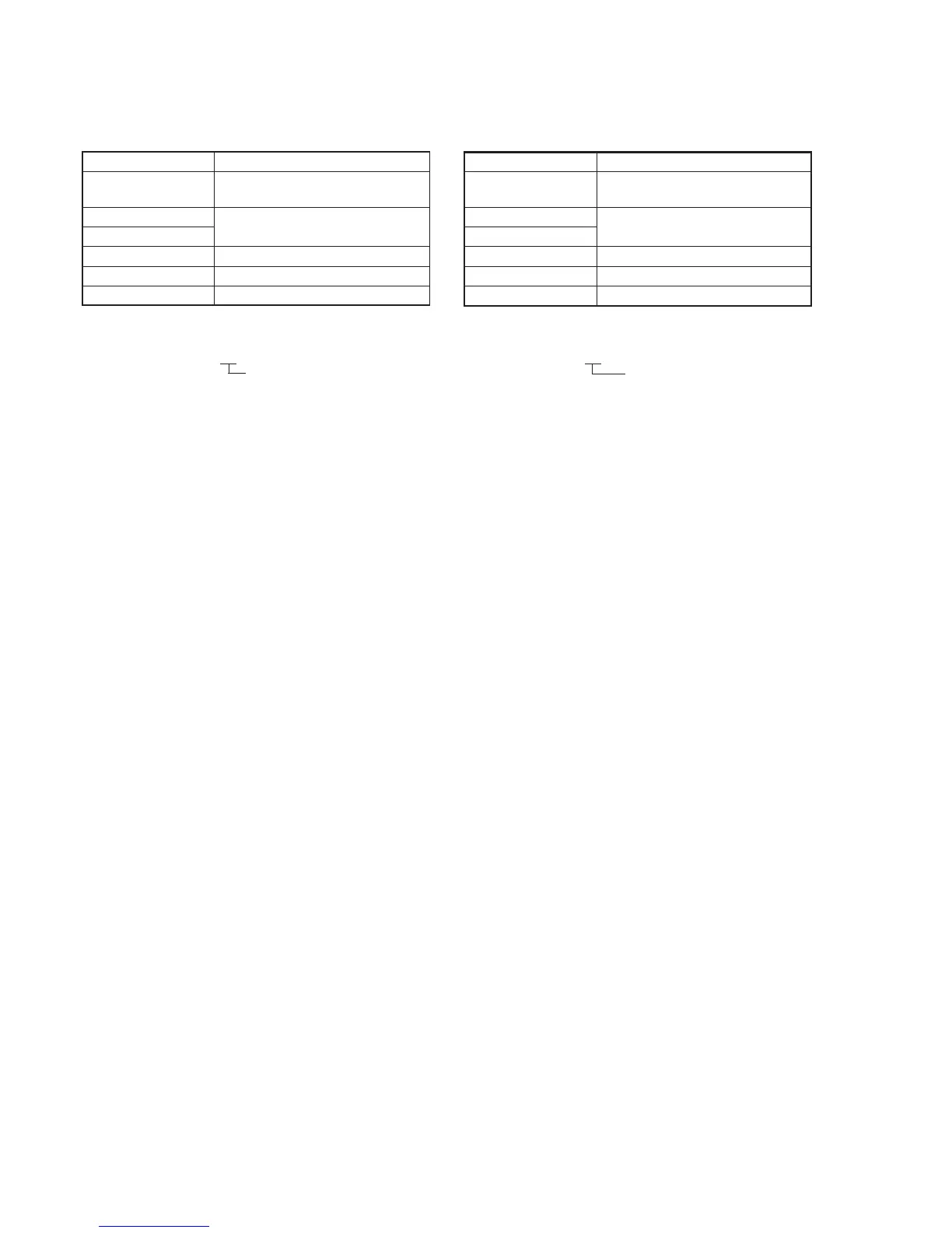
Set the clamp level of the CR AD OUT.
Mode VTR stop
Signal 75% color bar (Video signal terminal
of AUDIO/VIDEO jack)
Measurement Point DDS display of LCD or TV monitor
Measuring Instrument (Note)
Adjustment Page D
Adjustment Address B4
Specified Value FF or 00 or 01
Note: The two digits of the display data of the LCD and TV monitor is the
object data.
HI XX XXXX
Object data
Adjusting method:
1) Select page: 0, address: 01, and set data: 01.
2) Select page: D, address: 11, set data: 24, and press the PAUSE
button of the adjustment remote commander.
3) Select page: 2, address: 96, and set data: 40.
4) Select page: 2, address: 97, and set data: 18.
5) Select page: D, address: B4, set data: 4C, and press the PAUSE
button of the adjustment remote commander.
6) Select page: D, address: B5, set data: 4C, and press the PAUSE
button.
7) Select page: D, address: B4, change the data and adjust the
DDS display data (Note) to the specified value. (The data of
address: B4 should be “00” to “99”.)
8) Press the PAUSE button of the adjustment remote commander.
9) Perform “IC9004 CB clamp Adjustment”.
Processing after Completing Adjustments:
1) Select page: D, address: 11, set data: 00, and press the PAUSE
button of the adjustment remote commander.
2) Select page: 0, address: 01, and set data: 00.
3) Select page: 2, address: 96, and set data: 00.
4) Select page: 2, address: 97, and set data: 00.
13. IC9004 CB clamp Adjustment (VI-148 Board)
(Except AEP/UK model)
Set the clamp level of the CB AD OUT.
Mode VTR stop
Signal 75% color bar (Video signal terminal
of AUDIO/VIDEO jack)
Measurement Point DDS display of LCD or TV monitor
Measuring Instrument (Note 1)
Adjustment Page D
Adjustment Address B5
Specified Value FF or 00 or 01
Note 1: The two digits of the display data of the LCD and TV monitor is
the object data.
HI XX XXXX
Object data
Note 2: Perform “IC9004 CR clamp Adjustment” before this adjustment.
Adjusting method:
1) Select page: 0, address: 01, and set data: 01.
2) Select page: D, address: 11, set data: 24, and press the PAUSE
button of the adjustment remote commander.
3) Select page: 2, address: 96, and set data: 40.
4) Select page: 2, address: 97, and set data: 18.
5) Select page: D, address: B5, change the data and adjust the
DDS display data (Note 1) to the specified value. (The data of
address: B5 should be “00” to “99”.)
6) Press the PAUSE button of the adjustment remote commander.
Processing after Completing Adjustments:
1) Select page: D, address: 11, set data: 00, and press the PAUSE
button of the adjustment remote commander.
2) Select page: 0, address: 01, and set data: 00.
3) Select page: 2, address: 96, and set data: 00.
4) Select page: 2, address: 97, and set data: 00.
 Loading...