5-49
5. IC9004 AGC Adjustment (VI-148 Board)
(Except AEP/UK model)
Set the AGC gain.
Mode VTR stop
Signal 75% color bar (Video signal terminal
of AUDIO/VIDEO jack)
Measurement Point Y signal terminal of S VIDEO jack
(75 Ω terminated)
Measuring Instrument Oscilloscope
Adjustment Page D
Adjustment Address 9A
Specified Value A = 1.00 ± 0.02V
Note 1: Insert a plug in the S VIDEO jack.
Note 2: Before perform this adjustment, check that the specified value of
“S-Y Output Level Adjustment” is satisfied.
Adjusting method:
1) Select page: 0, address: 01, and set data: 01.
2) Select page: 2, address: 13, and set data: FE.
3) Select page: D, address: 9A, change the data and set the Y
signal level (A) to the specified value.
4) Press the PAUSE button of the adjustment remote commander.
5) Select page: 2, address: 13, and set data: 00.
6) Select page: 0, address: 01, and set data: 00.
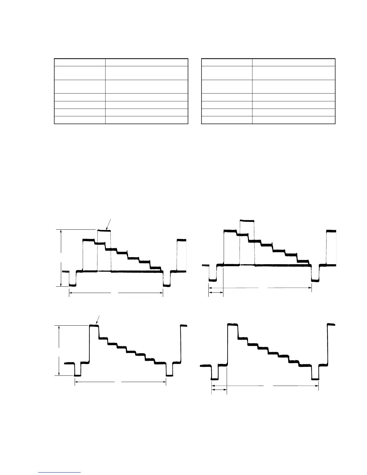
For NTSC model
For PAL model
Fig. 5-3-13
H
A
White (100%)
A
White (100%)
H
6. AFC TC Adjustment (VI-148 Board)
(Except AEP/UK model)
Set the picture frame in recording.
Mode VTR stop
Signal 75% color bar (Video signal terminal
of AUDIO/VIDEO jack)
Measurement Point Y signal terminal of S VIDEO jack
(75 Ω terminated)
Measuring Instrument Oscilloscope
Adjustment Page D
Adjustment Address A2
Specified Value t2-t1 = 0 ± 0.05 µ sec
Note: Insert a plug in the S VIDEO jack.
Adjusting method:
1) Select page: 0, address: 01, and set data: 01.
2) Select page: 2, address: 13, and set data: FE.
3) Check the delay time (t1).
4) Select page: 2, address: 13, and set data: FF.
5) Select page: D, address: A2, change the data so that the delay
time (t2) is equal to the delay time (t1) of step 3).
6) Press the PAUSE button of the adjustment remote commander.
7) Select page: 2, address: 13, and set data: 00.
8) Select page: 0, address: 01, and set data: 00.
For NTSC model
For PAL model
Fig. 5-3-14
 Loading...