— 6 —
DCR-TRV9/TRV9E
SERVICE NOTE
1. POWER SUPPLY DURING REPAIRS
In this unit, about 10 seconds after power is supplied (8.4V) to the
battery terminal using the service power cord (J-6082-223-A), the
power is shut off so that the unit cannot operate.
This following two methods are available to prevent this. Take note
of which to use during repairs.
Method 1.
Connect the servicing remote commander RM-95 (J-6082-053-B)
to the LANC jack, and set the remote commander switch to the
“ADJ” side.
Method 2.
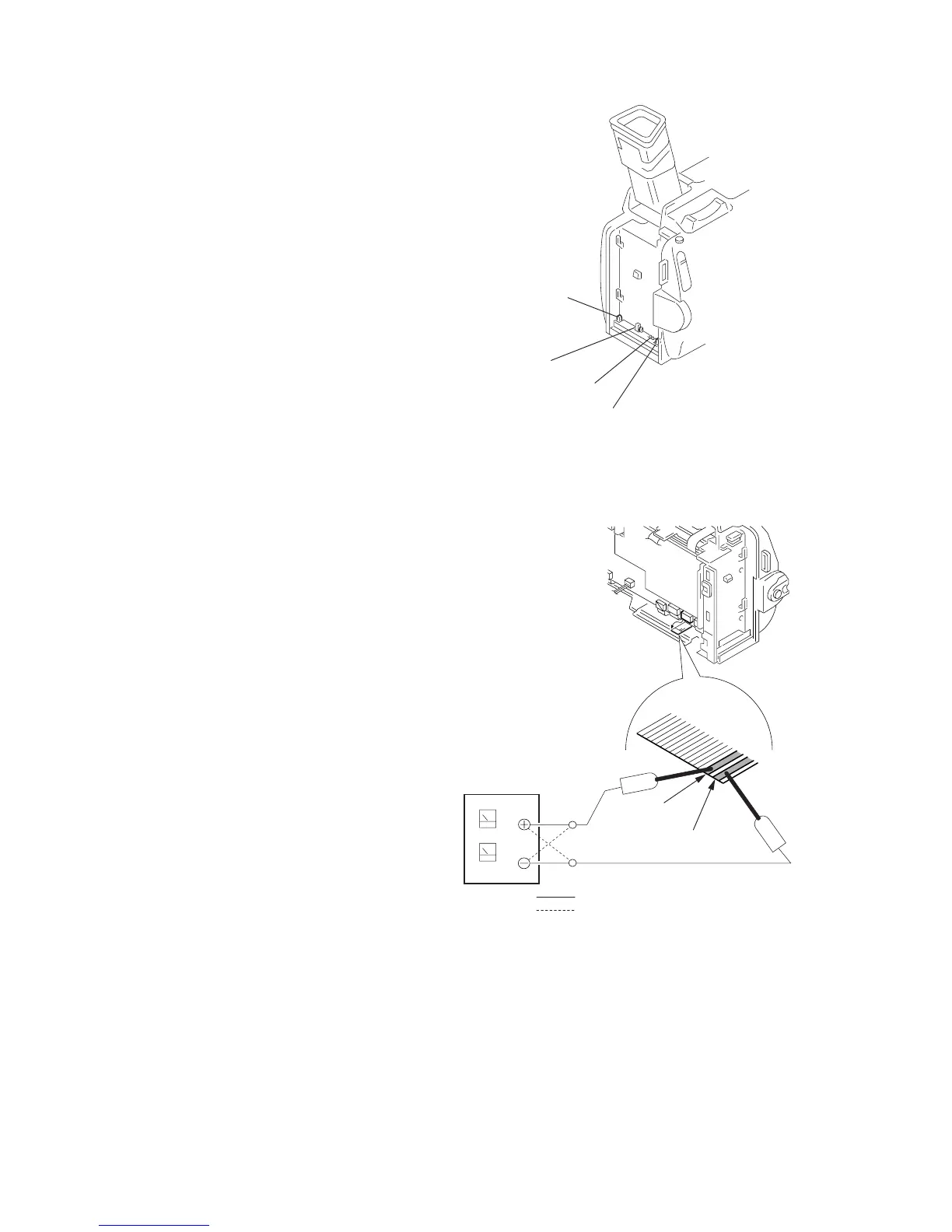
Press the following battery switch using adhesive tape, etc.
2. HOW TO TAKE A CASSETTE OUT
WHEN THE MAIN POWER CANNOT
BE TURNED ON
Note: To take a cassette out forcibly as follows when the main power
cannot be turned on, remove the cabinet (R) assembly. Apply +4.5
V power from an external power supply to the FP-594 flexible board
that is removed from CN3106 of the VC-206 board, as shown below.
Refer to sections 2-1 and 2-2 for the procedure to remove the cabinet
(R) assembly.
Procedure:
1) Open the cassette lid.
2) Apply +4.5 V directly to the FP-594 flexible board as shown to
drive the loading motor that ejects a cassette.
Battery terminal
‘
Battery switch
Battery SIG terminal
Battery terminal
’
FP-594
flexible
board
Pins-24/-25
(wide pattern)
1
27
Pin-26/-27
(wide pattern)
: unloading
: loading
 Loading...