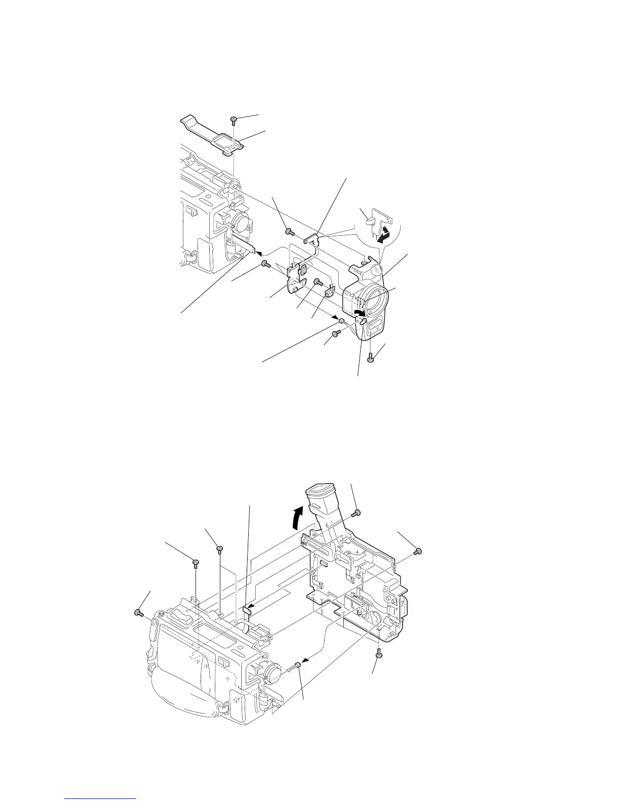
EasyManuals Logo

Sony DCR-TRV9 Service Manual

Sony DCR-TRV9
176 pages
To Next Page IconTo Next Page
To Previous Page IconTo Previous Page
Page #32 background imageLoading...
Page #32 background image
2-1
DCR-TRV9/TRV9E
SECTION 2
DISASSEMBLY
NOTE: Follow the disassembly procedure in the numerical order given.
2-1. F PANEL ASSEMBLY
1
Screw (M2
×
4)
2
FP-654 flexible board
6
Screw (B2
×
5)
4
Screw (B2
×
5)
0
MA-322 board
Front panel assembly
3
Function switch block
(MF-4580)
(from CN7002 of MA-322 board
)
0
MA-322 board
0
MA-322 board
9
Screw (B2
×
5)
1
Screw
(M2
×
4)
7
Connector
(from CN7003 of MA-322 board)
8
Open the jack cover.
1
Screw (M2
×
4)
Claw
5
!⁄
Cabinet (Upper)
2-2. CABINET (L), CABINET (R) ASSEMBLIES
2
Screw (M2
×
3)
4
Screw (M2
×
4)
5
Screw (M2
×
4)
4
Screw (M2
×
4)
1
Screw (M2
×
3)
6
Screw (M2
×
4)
8
Harness (BT-55)
(from CN9831 of LI-64 board)
*
Be careful that the harness is fragile and can be easily broken.
In addition, when this harness is removed, the memory backup
power is turned off, and setting of the user's memory
becomes necessary.
7
FP-650 flexible board
(from CN7805 of KY-39 board)
3

Table of Contents

Questions and Answers:

Question and Answer IconNeed help?

Do you have a question about the Sony DCR-TRV9 and is the answer not in the manual?

Sony DCR-TRV9 Specifications

General IconGeneral
BrandSony
ModelDCR-TRV9
CategoryCamcorder
LanguageEnglish

Related product manuals