5-36
3-1-4. Connecting the Equipment
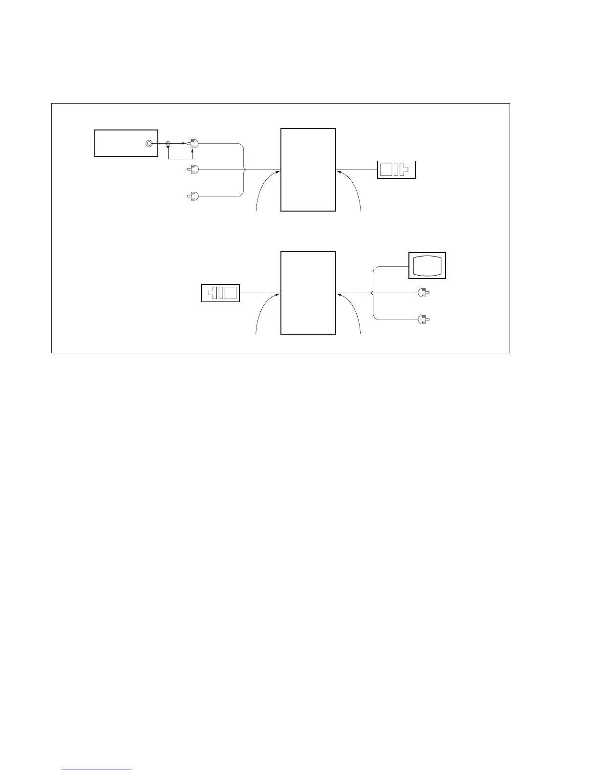
Connect the measuring instruments as shown in Fig. 5-3-2, and
perform the adjustments.
Fig. 5-3-2
Adjustment
remote
commander
LANC jack
Main unit
AUDIO/VIDEO jack
TV monitor
VIDEO
(Yellow)
AUDIO L (White)
AUDIO R (Red)
Main unit
LANC jack
AUDIO/VIDEO jack
Adjustment
remote
commander
VIDEO
(Yellow)
AUDIO L
(White)
AUDIO R
(Red)
Pattern generator
Video output
(75
Ω
)
VTR recording mode (Except AEP/UK model)
Playback mode
3-1-5. Checking the Input Signals
(Except AEP/UK model)
Because the video signal obtained from the pattern generator is used
as the adjustment signal for adjusting the VTR section, the video
output signal must satisfy the given specifications. Connect the
oscilloscope to the video terminal of the AUDIO/VIDEO jack, and
check that the sync signal amplitude of the video signal is
approximately <0.286V> [0.30V], the amplitude of the video section
is approximately <0.714> [0.70V], the amplitude of the burst signal
is approximately <0.286> [0.30V] and flat, and that the level ratio
of the burst signal to the “red“ signal is 0.30 : 0.60. The video signal
used for adjusting the video section is shown in Fig. 5-3-3.
< > : NTSC model
[ ] : PAL model
 Loading...