5-47
3-5-3. Base Band Block Adjustments
1. Composite Output Y Level Adjustment
(VC-206 Board)
Set the Y signal level of the composite video output signal.
Mode VTR stop
Signal No signal
Measurement Point Video signal terminal of AUDIO/
VIDEO jack (75 Ω terminated)
Measuring Instrument Oscilloscope
Adjustment Page D
Adjustment Address 96
Specified Value A = 286 ± 6 mV (NTSC)
A = 300 ± 6 mV (PAL)
Note: Insert a plug in the AUDIO/VIDEO jack.
Adjusting method:
1) Select page: 0, address: 01, and set data: 01.
2) Select page: D, address: 15, after memorizing the data, set the
bit value of bit2 to “0”. (Refer to “4-3, 3. Bit value
discrimination” of “5-4. Service Mode”).
3) Select page: D, address: 96, change the data and set the Y signal
level (A) to the specified value.
4) Press the PAUSE button of the adjustment remote commander.
5) Select page: D, address: 15, and set the data memorized at step
2).
6) Press the PAUSE button of the adjustment remote commander.
7) Select page: 0, address: 01, and set data: 00.
8) Perform “Composite Output Chroma Level Adjustment”.
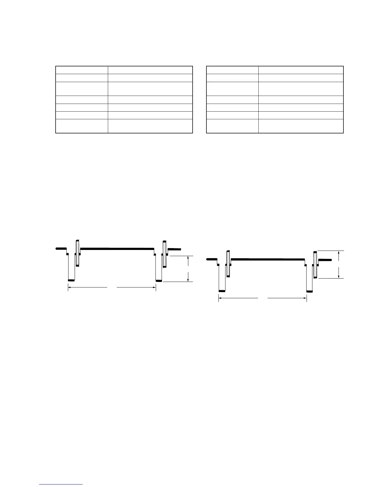
Fig. 5-3-9
A
H
2. Composite Output Chroma Level Adjustment
(VC-206 Board)
Set the chroma signal level of the composite video output signal.
Mode VTR stop
Signal No signal
Measurement Point Video signal terminal of AUDIO/
VIDEO jack (75 Ω terminated)
Measuring Instrument Oscilloscope
Adjustment Page D
Adjustment Address 97
Specified Value A = 286 ± 6 mV (NTSC)
A = 300 ± 6 mV (PAL)
Note 1: Insert a plug in the AUDIO/VIDEO jack.
Note 2: Perform “Composite Output Chroma Level Adjustment” before
this adjustment.
Adjusting method:
1) Select page: 0, address: 01, and set data: 01.
2) Select page: D, address: 15, after memorizing the data, set the
bit value of bit2 to “0”. (Refer to “4-3, 3. Bit value
discrimination” of “5-4. Service Mode”).
3) Select page: D, address: 97, change the data and set the burst
signal level (A) to the specified value.
4) Press the PAUSE button of the adjustment remote commander.
5) Select page: D, address: 15, and set the data memorized at step
2).
6) Press the PAUSE button of the adjustment remote commander.
7) Select page: 0, address: 01, and set data: 00.
8) Perform “S-C Output Level Adjustment”.
Fig. 5-3-10
A
H
 Loading...