5-35
3-1-2. Precautions on Adjusting
1) The adjustments of this unit are performed in the VTR mode
or camera mode.
To set to the VTR mode, set the power switch to “VTR” (or
“PLAYER”) or set the “Forced VTR Power ON mode” using
the adjustment remote commander (Note 1). To set to the
Camera mode, set the power switch to “CAMERA“ or set the
“Forced Camera Power ON mode” using the adjustment remote
commander (Note 2). After completing adjustments, be sure to
exit the “Forced VTR Power ON Mode” or “Forced Camera
Power ON Mode”. (Note 3)
2) The front panel block (MA-322 board, microphone unit, focus
ring) need not be connected except during “Battery End
Adjustment”, “IR Transmitter Adjustments” and “Audio
adjustments”. To remove, disconnect the following connectors.
VC-206 board CN9905 (27P, 0.3mm)
3) The lens block (CD-185 board) need not be connected except
during “Battery End Adjustment”. To remove, disconnect the
following connectors.
VC-206 board CN201 (50P, 0.5mm)
4) The intelligent accessory shoe need not be assembled. If
removing it. Disconnect the following connector.
VC-206 board CN9908 (9P, 0.5mm)
5) Cabinet (R) ( Camera function switch (KY-39 board, CF-4580
block), LCD block, viewfinder) need not be connected. But
removing the cabinet (R) (removing the VC-206 board CN9912)
means removing the lithium 3V power supply (LI-64 board) ,
data such as date, time, user-set menus will be lost. After
completing adjustments, reset these data. If the cabinet (R) has
been removed, the self-diagnosis data, data on history of use
(total drum rotation time etc.) will be lost. Before removing,
note down the self-diagnosis data and the data on the history
use (data of page: 2, address: 35 to 3D). (Refer to the “Service
Mode” for the data on the history use.) To remove the cabinet
(R), disconnect the following connectors.
1. VC-206 board CN9909 (50P, 0.5mm)
2. VC-206 board CN9912 (2P, 1.5mm)
Note 1: Setting the “Forced VTR Power ON” mode (VTR mode)
1) Select page: 0, address: 01, and set data: 01.
2) Select page: D, address: 10, set data: 02, and press the PAUSE
button of the adjustment remote commander.
The above procedure will enable the VTR power to be turned
on with the power switch block (PS-4580) removed.
After completing adjustments, be sure to exit the “Forced VTR
Power ON mode”.
Note 2: Setting the “Forced Camera Power ON” mode
(Camera mode)
1) Select page: 0, address: 01, and set data: 01.
2) Select page: D, address: 10, set data: 01, and press the PAUSE
button of the adjustment remote commander.
The above procedure will enable the camera power to be turned
on with the power switch block (PS-4580) removed.
After completing adjustments, be sure to exit the “Forced
Camera Power ON mode”.
Note 3: Exiting the “Forced Power ON” mode
1) Select page: 0, address: 01, and set data: 01.
2) Select page: D, address: 10, set data: 00, and press the PAUSE
button of the adjustment remote commander.
3) Select page: 0, address: 01, and set data: 00.
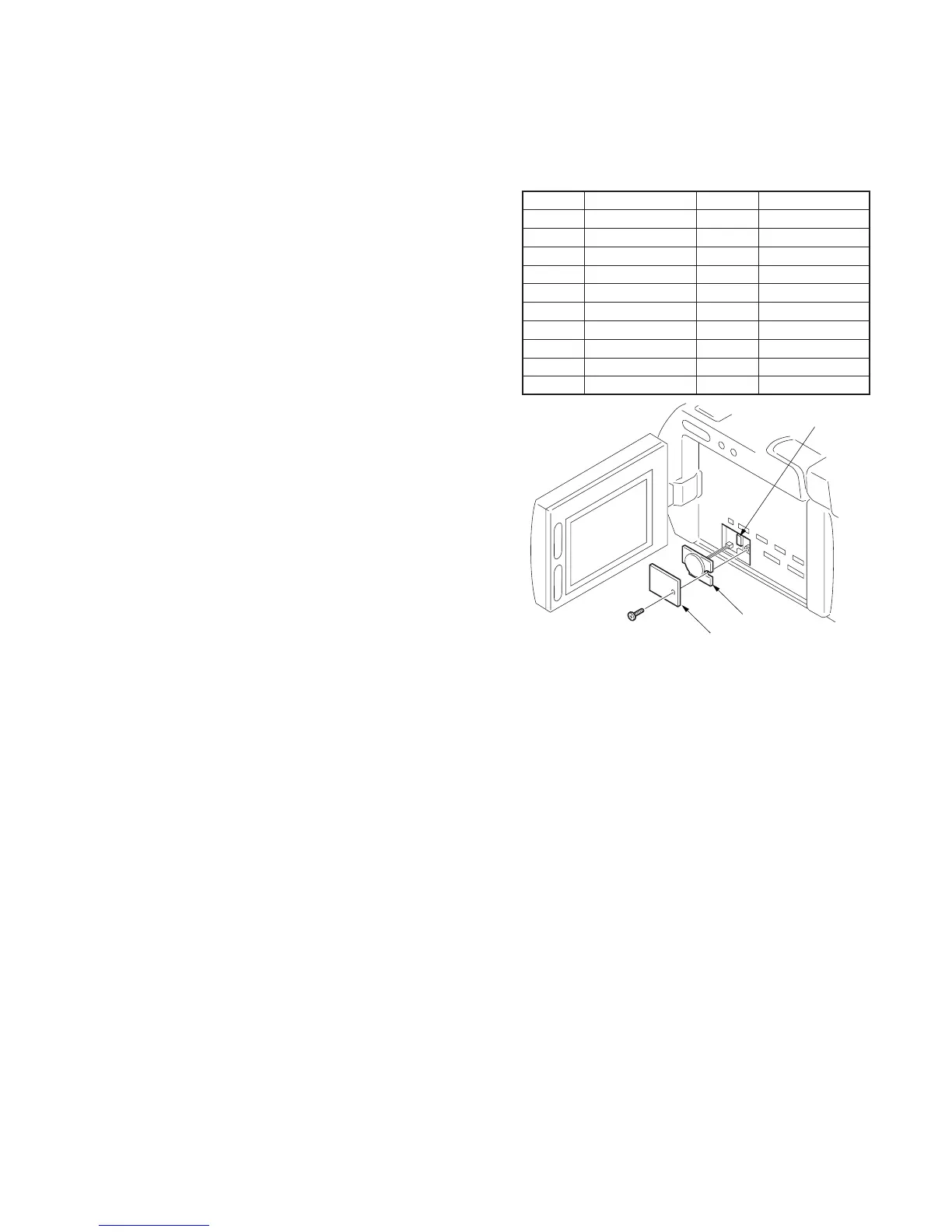
3-1-3. Adjusting Connectors
Some of the adjusting points of the video section are concentrated
at VC-206 board CN9903. Connect the measuring instruments via
the CPC-8 jig (J-6082-388-A). The following table lists the pin
numbers and signal names of CN9903.
Fig. 5-3-1
Pin No.
1
3
5
7
9
11
13
15
17
19
Signal Name
TCK
TDI
AFC ERR
IR FSC
VCC2
VCC1
LOCK
ENV OUT
TDO8
DEC B-Y
Pin No.
2
4
6
8
10
12
14
16
18
20
Signal Name
TMS
GND
JSWP
RF MONITOR
AGC IN
EQ IN
EVF BL 4.75V
EVF 4.75V (–)
VCO
EVF VG
CN9903 (CPC
 Loading...