5-43
3-5. VIDEO SYSTEM ADJUSTMENTS
Before perform the video system adjustments, check that the
specified value of “36 MHz Origin Oscillation Adjustment” of
“CAMERA SYSTEM ADJUSTMENT” is satisfied.
3-5-1. RF Block Adjustments
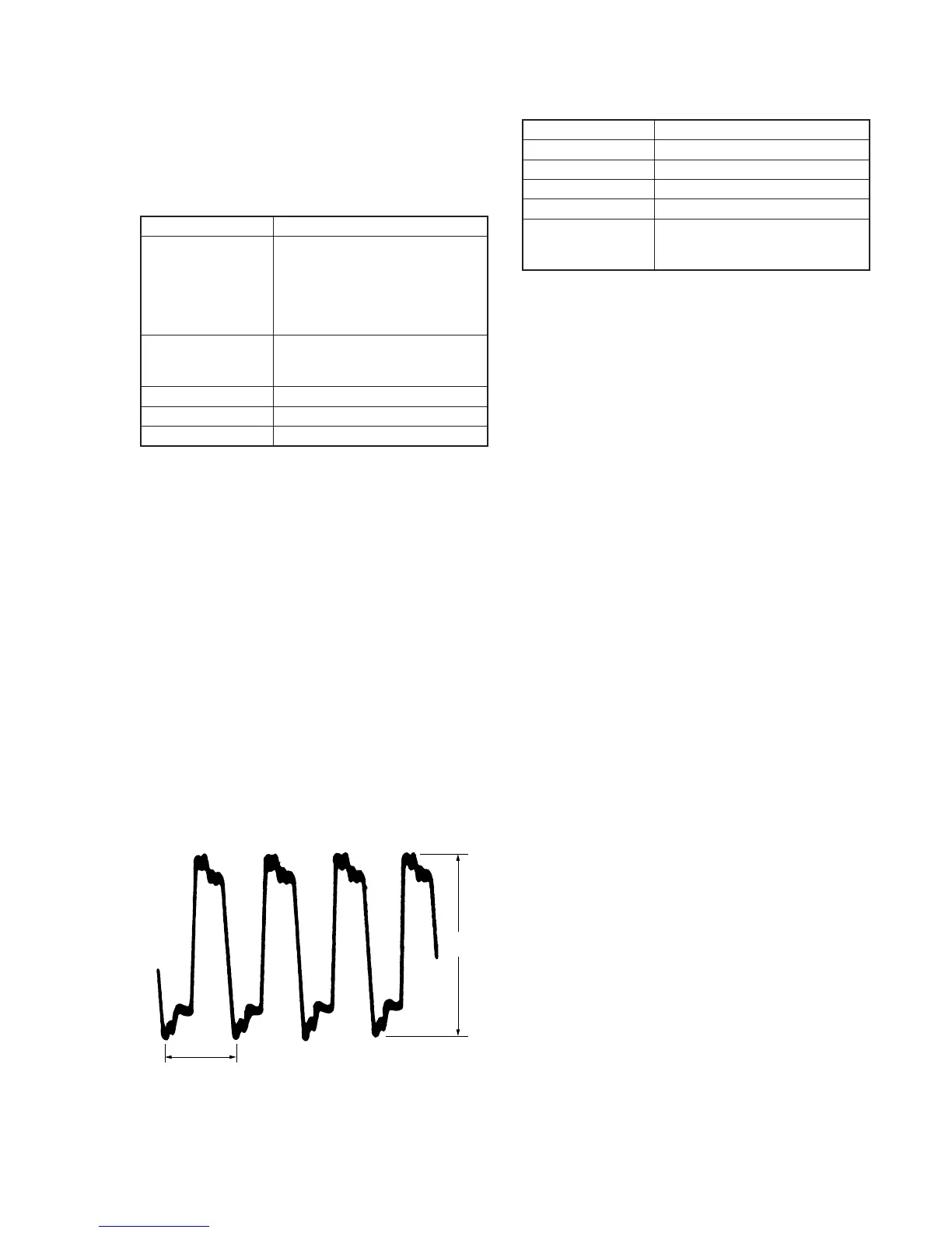
1. Recording Current Adjustment (VC-206 Board)
Mode VTR stop
Measurement Point ODDch adjustment
CH1: Pin 5 of CN2701 (CL2718)
CH2: Pin 6 of CN2701 (CL2719)
EVENch adjustment
CH1: Pin 9 of CN2701 (CL2722)
CH2: Pin 8 of CN2701 (CL2721)
Measuring Instrument Oscilloscope
ADD mode
CH2 INV mode
Adjustment Page C
Adjustment Address 3E, 3F
Specified Value A = 3.1 ± 0.1 Vp-p
Connection:
Disconnect CN2701 and connect as follows.
1) ODDch adjustment: Connect a 180 Ω resistor between Pin 5
of CN2701 (CL2718) and Pin 6 of CN2701 (CL2719).
2) EVENch adjustment: Connect a 180 Ω resistor between Pin
9 of CN2701 (CL2722) and Pin 8 of CN2701 (CL2721).
180 Ω resistor (Parts code: 1-249-408-11)
Adjusting method:
1) Equalize the vertical range of CH1 and CH2 of the oscilloscope.
2) Set the oscilloscope to the ADD mode, and set CH2 to the INV
mode.
3) Select page: 0, address: 01, and set data: 01.
4) Select page: 3, address: 01, set data: 0C, and press the PAUSE
button of the Adjustment remote commander.
5) Select page: 3, address: 34, and set data: 01.
6) Select page: C, address: 3F (ODDch adjustment) or address:
3E (EVENch adjustment), change the data and adjust the signal
voltage (A) to the specified value.
7) Press the PAUSE button of the adjustment remote commander.
8) Select page: 3, address: 34, and set data: 04.
9) Select page: 3, address: 01, set data: 00, and press the PAUSE
button of the Adjustment remote commander.
10) Select page: 0, address: 01, and set data: 00.
Fig. 5-3-5
A
0.1
µ
sec
2. PLL f0 Adjustment (VC-206 Board)
Mode VTR stop
Measurement Point Display data of page: 3, address: 04
Measuring Instrument Adjustment remote commander
Adjustment Page C
Adjustment Address 3C, 3D
Specified Value Displayed data is “FD” to “FF” or
“00” to “03”. (“FF”, “00” are center
values)
Adjusting method:
1) Select page: 0, address: 01, and set data: 01.
2) Select page: 3, address: 01, set data: 05, and press the PAUSE
button of the Adjustment remote commander.
3) Select page: 3, address: 36, and set data: 04.
4) Select page: 3, address: 04, and check that the average value
D04 of the displayed data is “FD” to “FF” or “00” to “03”. If
outside this range, change the data of page: C, address: 3C,
and check again.
[ If D04 is “80” to “FC” ]
Decrease the data of page: C, address: 3C. (As the data is to be
rewritten, press the PAUSE button of the adjusting remote
commander.)
[ If D04 is “04” to “7F” ]
Increase the data of page: C, address: 3C. (As the data is to be
rewritten, press the PAUSE button of the adjusting remote
commander.)
5) Select page: 3, address: 36, and set data: 05.
6) Select page: 3, address: 04, and check that the average value
D04 of the displayed data is “FD” to “FF” or “00” to “03”. If
outside this range, change the data of page: C, address: 3D,
and check again.
[ If D04 is “80” to “FC” ]
Decrease the data of page: C, address: 3D. (As the data is to be
rewritten, press the PAUSE button of the adjusting remote
commander.)
[ If D04 is “04” to “7F” ]
Increase the data of page: C, address: 3D. (As the data is to be
rewritten, press the PAUSE button of the adjusting remote
commander.)
7) Select page: 3, address: 01, set data: 00, and press the PAUSE
button of the Adjustment remote commander.
8) Select page: 3, address: 36, and set data: 02.
9) Select page: 0, address: 01, and set data: 00.
 Loading...