In the 1st row, press
the button to which the
corresponding key
was assigned in the
Setup menu, turning it
on.
In the 1st row, press
the button to which
UTIL1 was assigned in
the Setup menu,
turning it on.
In the 1st row, press
the button to which the
corresponding bus
was assigned in the
Setup menu, turning it
on.
Frame
memory
source 1
and 2
buses
DME1,
DME2,
DME5 to
DME8
video
buses
a)
DME1,
DME2,
DME5 to
DME8 key
buses
a)
Number when
the shift button
is not pressed
Number when
the shift button
is pressed
From the left end to
the 23rd button
Chapter
3
Signal
Selection
and
Transitions
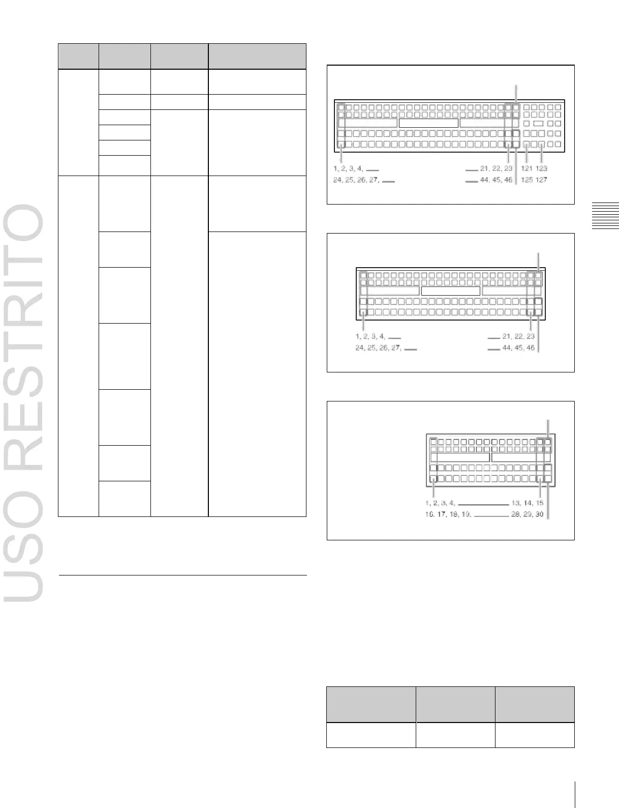
Cross-point control block button numbers
Shift buttons
(first button numbers)
(second button
numbers)
Shift buttons
Cross-point control block (ICP-6520/6530)
Shift buttons
(first button numbers)
(second button
numbers)
Shift buttons
Cross-point control block (ICP-3000)
Shift buttons
a)
DME1 and DME2 are enabled when using the MKS-6570 only. DME5 to
DME8 are enabled when using the MVE-8000A/9000 only.
b) MVS-6520/6530/3000A only
(first button numbers)
(second button numbers)
Cross-point control block (ICP-3016)
Shift buttons
On each switcher bank, each cross-point button and
Signal Assignment and Selection
Assigning signals to buttons
Each of the cross-point buttons and reentry buttons has a
corresponding button number, to which you assign a
signal.
In addition to the signals input to the connectors at the rear
of the switcher processor, you can also select signals
generated within the switcher.
Each button has assigned to it a video signal and a key
signal, forming a pair. You can set these video and key
combinations in the Setup menu.
reentry button has two button numbers, and you use the
shift button to switch between these numbers.
This section describes a unit with 24 cross-point buttons as
an example.
The button numbers on the cross-point control block are as
follows.
Cross-point control block button numbers
 Loading...


