Names and Functions of Parts of the Control Panel
Overview of assigned operation
• This enables the Programmable Effector
software operation mode.
• The operation applies to the [FX1] to [FX4]
and [ID1] to [ID4] buttons.
For details, refer to the Help for the MPES-
FX01 Programmable Effector software.
Overview of assigned operation
• These enable the positioner (wipe pattern
position setting) operation mode.
• You can select more than one button
simultaneously.
• These enable the three-dimensional
transform operation mode.
• You can select more than one button
simultaneously.
• The [DME1] and [DME2] buttons are
enabled only when using the MKS-6570.
• The [DME5] to [DME8] buttons are
enabled only when an MVE-8000A/MVE-
9000 is used.
• This enables the VTR/disk recorder/frame
memory operation mode.
• The operation applies to the [DEV1] to
[DEV12], [FM1 CLIP], [FM2 CLIP], and
[FM LOOP] buttons.
• You can also assign the [FM3 CLIP] to
[FM8 CLIP], [RECUE], and [LOOP]
buttons in the Setup menu.
This enables the keyframe operation mode.
• This enables the resizer operation mode.
• Use the [M/E1] or [P/P] button to select the
target switcher bank.
• The operation applies to the [K1RSZ] and
[K2RSZ] buttons.
Chapter
2
Names
and
Functions
of
Parts
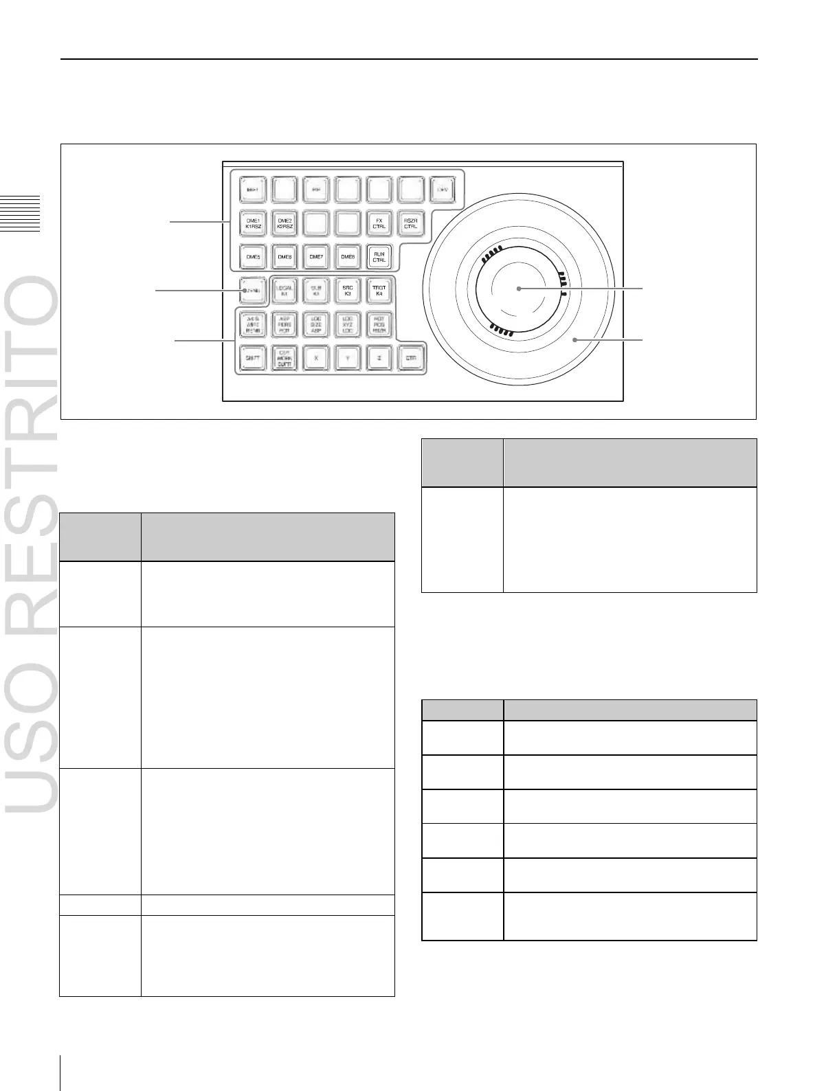
Device Control Block
The device control block is used for three-dimensional
transform operations using a DME, for wipe pattern
position setting, and for VTR/disk recorder/frame memory
clip operation.
1
Region selection
buttons
5
MENU button
3
Trackball
2
Operation buttons
4
Z-ring
a
Region selection buttons
The operation mode allocated to the device control block
depends on the selection state of the region selection
buttons.
b
Operation buttons
These perform various operations. The function of each
button varies with the operation mode.
When the positioner operation mode is enabled
These enable wipe pattern position setting
for keys 1 to 4.
This enables wipe pattern position setting for
normal transitions.
This enables the trackball to move the wipe
pattern in the X-axis and Y-axis directions.
These restrict which axes the trackball can
control to the X- or Y-axis.
This returns the pattern position to the center
of the screen.
CLR WORK
BUFR (clear
work buffer)
Press this twice in rapid succession to reset
all parameters on the target M/E or PGM/
PST to their initial values.
a)
You can configure settings in the Setup menu to allow simultaneous
selection of multiple buttons.
b)
For details about operations for keys 5 to 8,
1
“8-Keyer Operation”
(p. 412).
 Loading...


