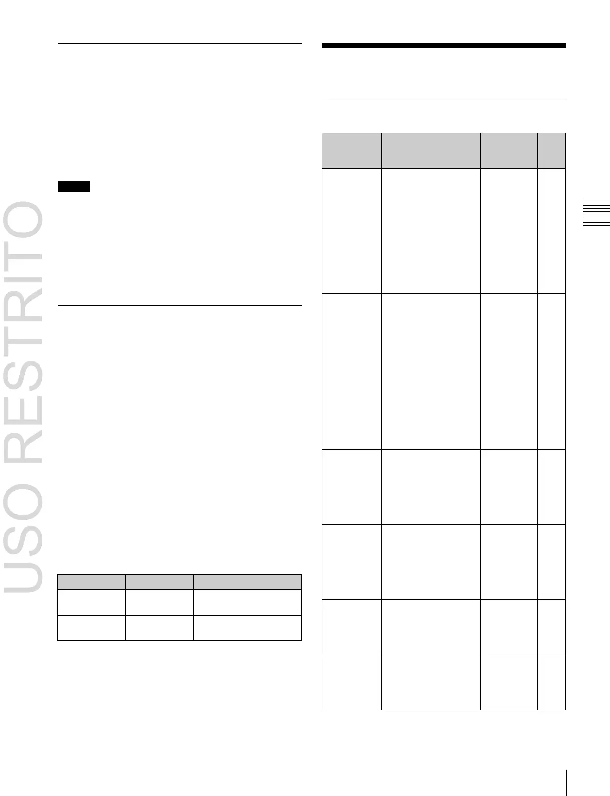
Independent
key
transition
The new video
progressively fades in
over the current video.
The sum of the two
video outputs is
maintained at a
constant, with the
output of each at 50%
at the mid-point of the
transition (i.e., when
the fader lever is in the
center position).
The current video and
new video signals are
compared, and the
signal with the higher
luminance level is
given priority in the
output. The signals are
compared at the mid-
point of the transition
when both signals are
at 100%, at which point
the signal with the
higher luminance level
overpowers the other
signal.
The current video is
maintained at 100%
output for the first half
of the transition as the
new video is mixed
while increasing
progressively to 100%.
The current video is
replaced by the new
video in a two-stage
transition, with a color
matte (unpatterned
display) inserted during
the first stage.
The current video is
replaced by the new
video according to a
predetermined wipe
pattern.
Using an image
transformation effect,
the current video is
replaced by the new
video as in a wipe.
Chapter
3
Signal
Selection
and
Transitions
Selecting Signals to be Linked with
the Audio Mixer
Transitions
When you select a signal in the background A row or 2nd
row of a switcher bank, and the bank and signal are linked
to an audio mixer, then the program output of the audio
mixer will switch along with the signal selection.
For details about settings,
1
“Making Settings for Audio
Mixer” (p. 332).
Transition Types
Notes
•
For details about audio mixers that can be connected,
contact your Sony service or sales representative.
•
When the signal is switched via a snapshot, keyframe, or
similar means, the audio mixer will not be linked.
•
When bus fixed mode is selected in the Setup menu
(
1
p. 73), the audio mixer program output is linked to
the bus output as the background.
Signal Name Display
You can attach a name (source name) to each signal
assigned to a cross-point button, with a maximum of 16
characters.
•
The source name displays in the cross-point control
block show the source names of the video signals
assigned to numbers 1 to 23 (or 1 to 15).
•
To display the source names for numbers 24 to 46 (or 16
to 30), press the following [SHIFT] button.
ICP-6520/6530: [SHIFT] button on the right of the
source name display.
ICP-3000/3016: [SHIFT] button assigned to the 1st row.
Colors of lit cross-point buttons
In a particular row of cross-point buttons, only the last
pressed button is effective, and lights amber or red. The
amber indicates the “low tally” state, and the red indicates
the “high tally” state, to indicate whether or not the
selected signal appears in the final output video.
Meaning of colors of lit cross-point buttons
Does not appear in final
output video.
Appears in final output
video.
 Loading...


