112 FS 240 C, FS 260 C, FS 360 C, FS 410 C, FS 460 C-M
12. Drive tube assembly
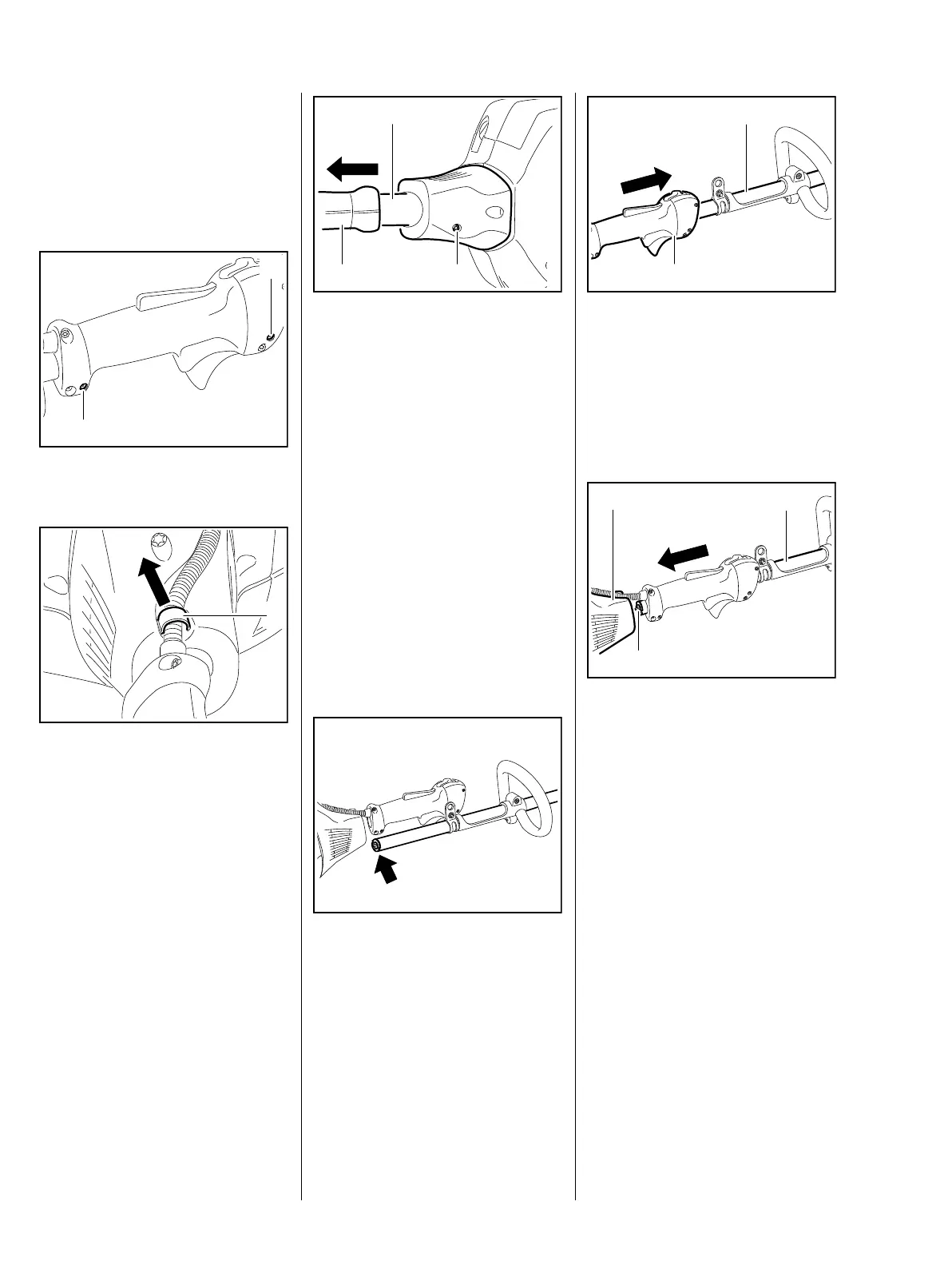
12.1 Drive tube assembly with
loop handle
Before removing the drive tube
assembly, the control handle for the
loop handle must be detached.
: Undo the screws (1)
: Ease out the cable holder (1)
5904RA441 TG
1
1
5904RA000 TG
1
: Undo the screw (1)
: Pull the drive tube assembly (2)
out of the clutch housing and
control handle for loop handle (3)
– Examine the drive tube
assembly, repair or replace if
necessary, b 12.2.1
With a new drive tube assembly, the
installed parts or components must
be converted.
Installation
– Degrease clamping area,
b 14
Loop handle and carrying ring must
be installed, b 12.2.3, b 12.3.3.
: Orient end of drive tube
assembly (arrow), with stopper
installed, so that it faces the
engine
5904RA442 TG
1
2
3
5904RA443 TG
The clamps in the control handle for
the loop handle must be loosened.
: Push the control handle for the
loop handle (1) onto the side of
the drive tube assembly (2), with
the stopper installed
: Push the drive tube assembly (1)
through the cover (2) in the clutch
housing with gentle twisting
motions until the square
profile (3) of the drive shaft
engages the clutch drum
The drive tube assembly must be
seated in the clamp as far as it will
go.
5904RA444 TG
1
2
5904RA445 TG
1
2
3
 Loading...