77FS 240 C, FS 260 C, FS 360 C, FS 410 C, FS 460 C-M
9. Antivibration elements
The vibration damping connection
between drive tube assembly and
clutch housing is made via a rubber
insert (1-point antivibration system)
or via rubber buffers, annular
buffers and springs (4-point
antivibration system).
Damaged rubber inserts, rubber
buffers, annular buffers or springs
must always be replaced.
9.1 Rubber insert
1-point antivibration system
– Remove the drive tube assembly,
b 12.1
– Remove the clutch housing and
clutch drum, b 4.1
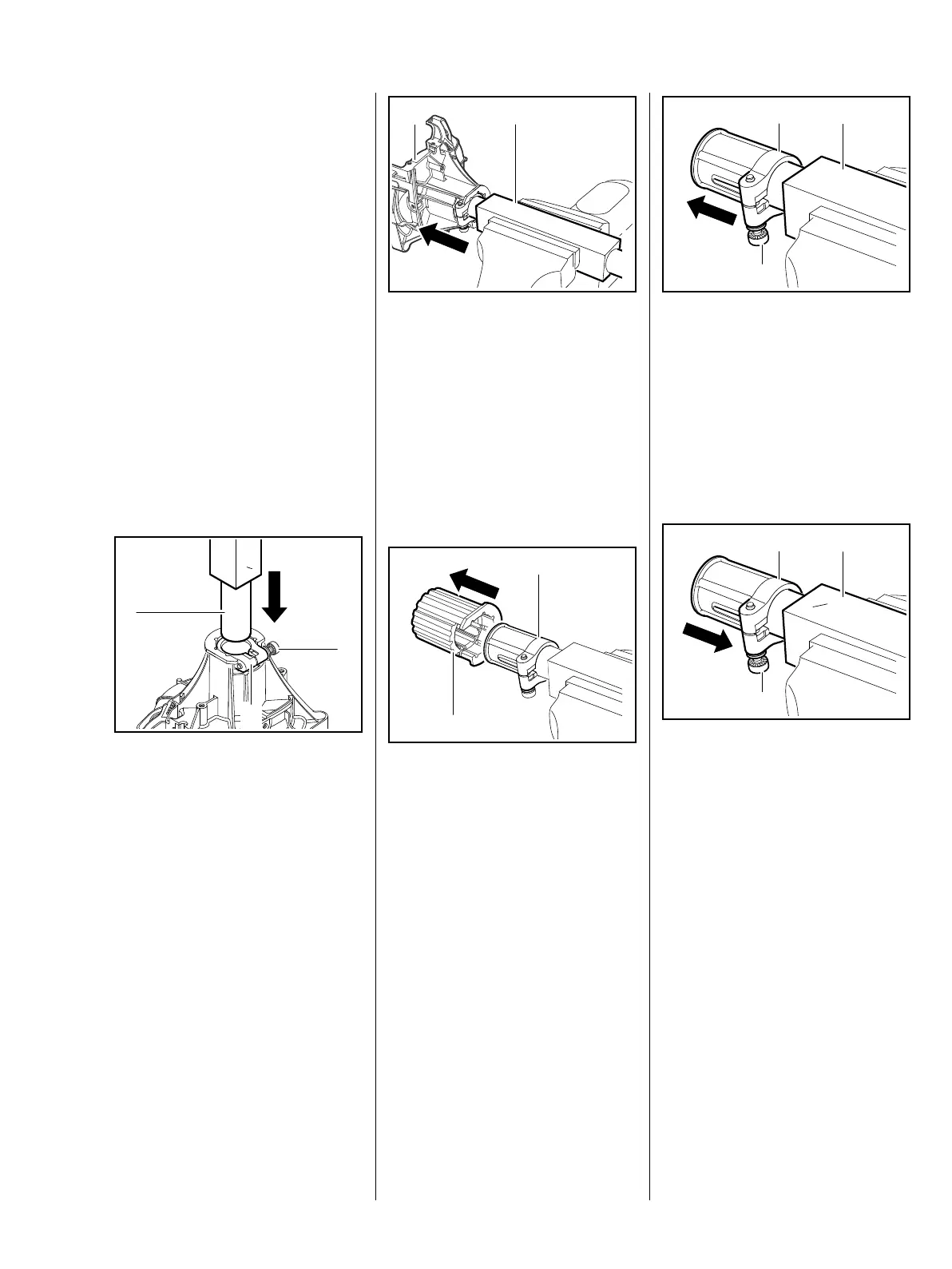
: Insert installing tool (1)
4126 893 4900 with the 25.4 mm
shaft into the clamp (2) as far as
it will go
: Tighten bolt (3)
O 25,4
5904RA213 TG
1
2
3
: Clamp square profile of installing
tool (1) with clutch housing (2) in
the vise
– Move the clutch housing back
and forth while apply sufficient
STIHL press fluid between clamp
and rubber insert, b 14
: Pull off clutch housing (2)
: Pull off rubber insert (1) from
clamp (2)
2
5904RA214 TG
1
1
2
5904RA216 TG
: Loosen bolt (1) and remove
clamp (2) from installation
tool (3)
– Examine clamp, rubber insert
and clutch housing, replace if
necessary
Installation
– Clamp square profile of installing
tool in vise
: Slide clamp (2) onto installing
tool (3) 4126 893 4900 with the
25.4 mm shaft as far as it will go
: Tighten bolt (1)
5904RA217 TG
1
2
3
O 25,4
5904RA218 TG
1
2
3
 Loading...