118 FS 240 C, FS 260 C, FS 360 C, FS 410 C, FS 460 C-M
Installation
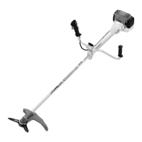
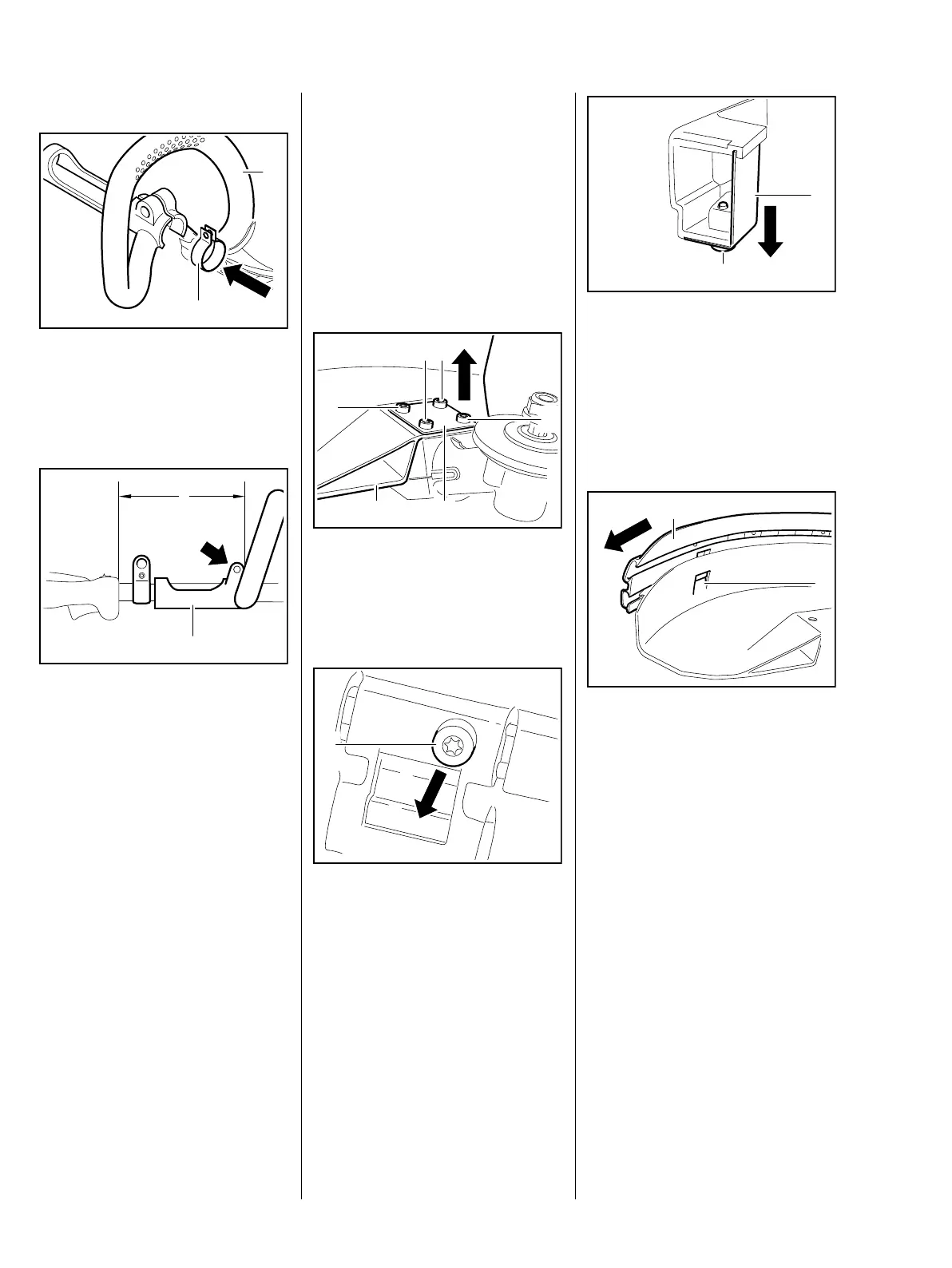
: Insert clamp (1) in loop handle (2)
– Fit screw
– do not tighten
– Install drive tube assembly,
b 12.1
: Orient loop handle (1) at a
distance of approx. a = 35 cm
from control handle and tighten
screw (arrow)
– Reassemble remaining parts in
reverse order
5904RA485 TG
1
2
1
5904RA543 TG
a
12.3 Deflector
12.3.1 Deflector for gearbox
with 25.4 mm drive tube
assembly diameter
To preserve the threads in the
plastic parts, screw the screws into
the existing threads and tighten
carefully.
: Remove screws (1)
: Remove plate (2) and deflector
(3)
: Unscrew the bolt (1)
– Push out mount with line limiting
blade
5904RA487 TG
3
1 1
1
1
2
5904RA488 TG
1
: Unscrew the bolt (1)
: Slide line limiting blade (2) down
slightly and remove
– Examine line limiting blade,
resharpen or replace if necessary
: Press tab (1) and slide out
strip (2)
– Examine gearbox, repair or
replace if necessary, b 12.4.2
5904RA489 TG
1
2
5904RA490 TG
2
1
 Loading...