85FS 240 C, FS 260 C, FS 360 C, FS 410 C, FS 460 C-M
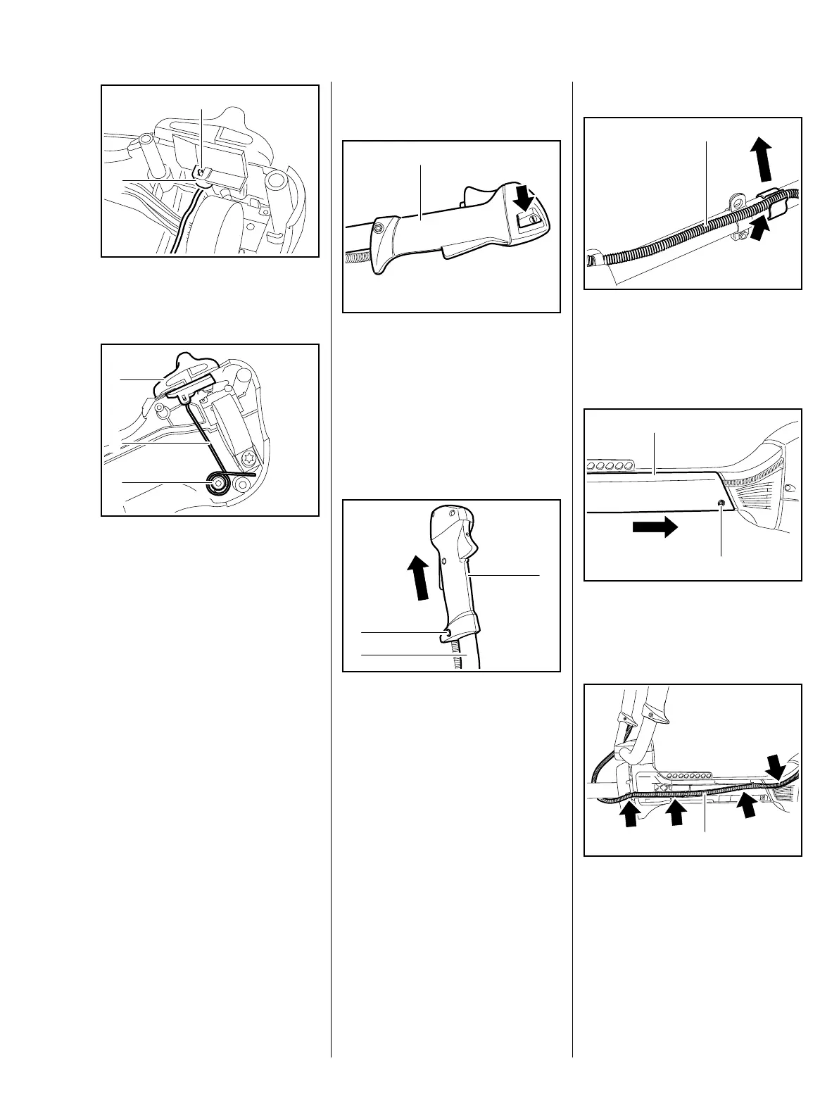
: The torsion spring (1) must be
seated in the mount (2)
: Check installation position of
torsion spring (2) and slide
control (1)
– see illustration
For the throttle trigger to be seated
correctly, the torsion spring (2) must
be pushed onto the post (3) over the
ribbed base
– Torsion spring is completely inside
the handle molding.
Checking operation
– Set slide control to position
STOP-0 , the contact spring must
actuate the microswitch – this
can be heard as a clicking noise
– Install throttle trigger / throttle
trigger interlock, b 10.1.1
– Check throttle cable setting,
adjust if necessary, b 10.2.4
– Reassemble remaining parts in
reverse order
5904RA297 TG
1
2
5904RA298 TG
1
2
3
10.2 Control handle for bike
handle
The control handle for bike
handle (1) with lever for stop
function (arrow) is pushed directly
onto the bike handle (diameter
25.4 mm or 22 mm) and secured
with a transverse screw.
10.2.1 Removal and installation
: Unscrew and remove the
screw (1), remove nut on the
opposite side
: Remove control handle (2) from
bike handle (3)
5904RA299 TG
1
5904RA300 TG
11
3
2
1-point antivibration system
: Remove protective tube (1) from
the guide (arrow)
4-point antivibration system
: Remove screw (1), push
fairing (2) toward engine and
remove
: Remove protective tube (1) from
the guide (arrows)
– Examine throttle cable or short
circuit wire and replace if
necessary, b 6.6
– Examine actuating lever, replace
if necessary, b 10.2
5904RA301 TG
1
5904RA222 TG
1
2
5904RA257 TG
1
 Loading...