10
Symbol Explanation
Do not touch live parts for 10 minutes after disconnection from
the power sources.
Additional grounding point.
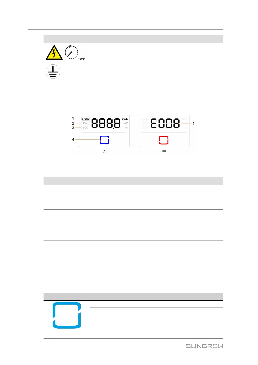
2.4 LED Indicator
The LED panel with a display screen and an indicator is on the front of the inverter.
figure 2-3 LED Panel
(a) Normal state (b) Error state
No. Name
Description
1
E-day Today’s energy yield
2 Pac
Real-time AC output power
3 SOC
Battery SOC (State of Charge)
4
LED
indicator
To indicate the working state of the inverter.
Touch it to switch the information in normal state or view multiple
error codes in error state.
5 Error code
The error code in the figure is just an example.
• In normal state, the E-day, Pac and SOC information will be displayed alternately. Also
you can touch the LED indicator to switch the information.
• In error state, touch the LED indicator to view multiple error codes.
• If there is no operation for 5 minutes, the display screen will be off. Touch the LED indica-
tor to activate it.
table 2-1 LED Indicator State Description
LED Color state Definition
Blue
ON
The inverter is running in the on/off-grid mode.
Blink
The inverter is at standby or startup state
(without on/off-grid operation).
2 Product Description User Manual
 Loading...