47
6.4.1 External Protective Grounding Requirements
All non-current carrying metal parts and device enclosures in the PV power system should
be grounded, for example, brackets of PV modules and inverter enclosure.
When there is only one inverter in the PV system, connect the external protective grounding
cable to a nearby grounding point.
When there are multiple inverters in the PV system, connect the external protective ground-
ing terminals of all inverters and the grounding points of the PV module brackets to ensure
equipotential connections to ground cables (according to the onsite conditions).
6.4.2 Connection Procedure
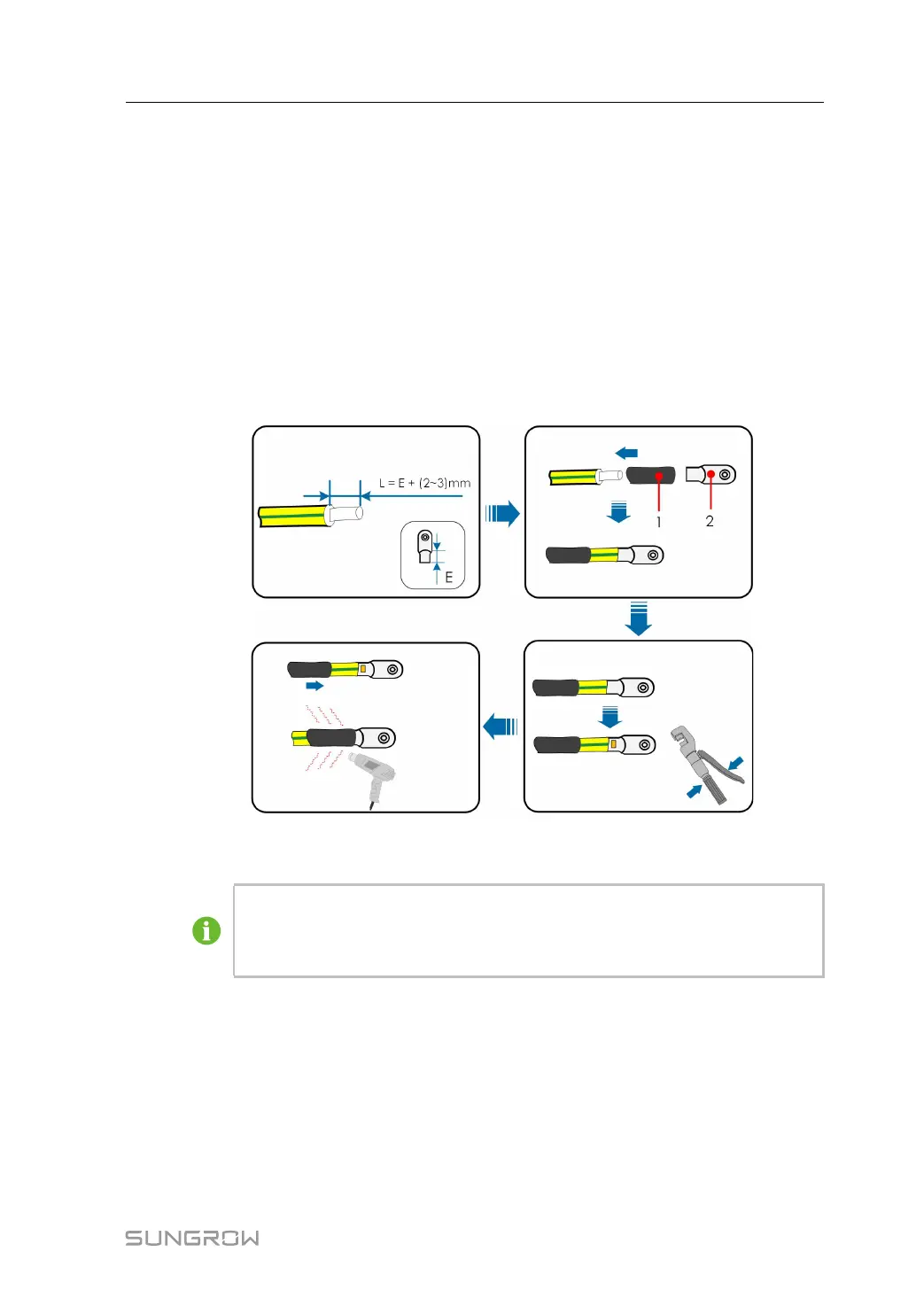
step 1 Prepare the cable and OT/DT terminal.
(1) Heat shrink tubing (2) OT/DT terminal
After being crimped, the OT terminal must wrap the wires completely, and the
wires must contact the OT terminal closely.
When using a heat gun, protect the device from being scorched.
step 2 Remove the screw on the grounding terminal and fasten the cable with a screwdriver.
step 3 Apply paint to the grounding terminal to ensure corrosion resistance.
- - End
User Manual 6 Electrical Connection
 Loading...