 Loading...
Do you have a question about the Suzuki df2.5 and is the answer not in the manual?
| Starting System | Manual |
|---|---|
| Fuel Tank Capacity | 1.0 L |
| Number of Cylinders | 1 |
| Full Throttle Operating Range | 5250 - 5750 RPM |
| Steering | Tiller |
| Displacement | 68 cm3 (4.2 cu.in.) |
| Max Output | 2.5 hp |
| Weight | 13.5 kg |
| Ignition System | CDI |
| Bore x Stroke | 48 x 38 mm (1.9 x 1.5 in.) |
Explains signal words (WARNING, CAUTION, NOTE) and general safety practices for servicing.
Details engine specifications, including dimensions, performance, and component data.
Lists specified torque values for various fasteners used in the outboard motor.
Lists specialized tools required for various maintenance procedures.
Outlines recommended intervals for all periodic service tasks based on operating hours or time.
Step-by-step guide for checking and changing engine oil, gear oil, and performing lubrication.
Covers spark plug inspection/replacement, valve clearance adjustment, and idle speed setting.
Procedures for checking ignition timing and inspecting fuel system components like the carburetor.
Details service intervals and procedures for water pump, propeller, and anode components.
Describes the ignition system and provides troubleshooting steps for starting issues.
Details inspection of igniter unit, spark plug cap, and air gap for proper function.
Covers removal and installation of flywheel magneto and igniter unit.
Emphasizes safety measures due to gasoline's flammability and toxicity.
Procedures for fuel line removal/installation and carburetor disassembly/reassembly.
Covers inspection and installation of the fuel tank and fuel cock assembly.
Step-by-step guide for removing and disassembling the recoil starter assembly.
Covers inspection of recoil starter components and reassembly procedures.
Outlines the procedure for removing and installing the entire power unit.
Details removal, installation, and inspection of cylinder head, valves, and rocker arm assemblies.
Covers disassembly, inspection, and reassembly of core engine internal components.
Instructions for thermostat removal, inspection, and installation.
Procedures for disassembling mid unit housing, brackets, and related parts.
Inspection criteria and reassembly steps for mid unit components.
Covers removal, disassembly, and reassembly of the tiller handle assembly.
Detailed steps for removing and disassembling the lower unit and its components.
Inspection criteria for propeller, gearcase, gears, and shaft components.
Procedures for reassembling the lower unit and adjusting gears, including oil filling.
Critical procedures for adjusting gear backlash and tooth contact patterns for proper gear engagement.
Illustrates fuel and breather hose routing with installation cautions.
Diagrams showing wire routing and the ignition system wiring schematic.
Introduces the supplementary manual and outlines general information changes for the 2008 model.
Details updated specifications and service data for the 2008 model.
Notes changes in periodic maintenance schedules and ignition timing for later models.
Covers changes to the fuel pump (US market) and carburetor settings for later models.
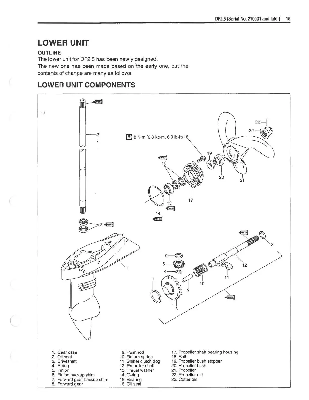
Details design changes in the lower unit and propeller shaft components for later models.
Covers replacement of driveshaft oil seals and illustrates updated wire routing for later models.