FI
SYSTEM DIAGNOSIS
4-21
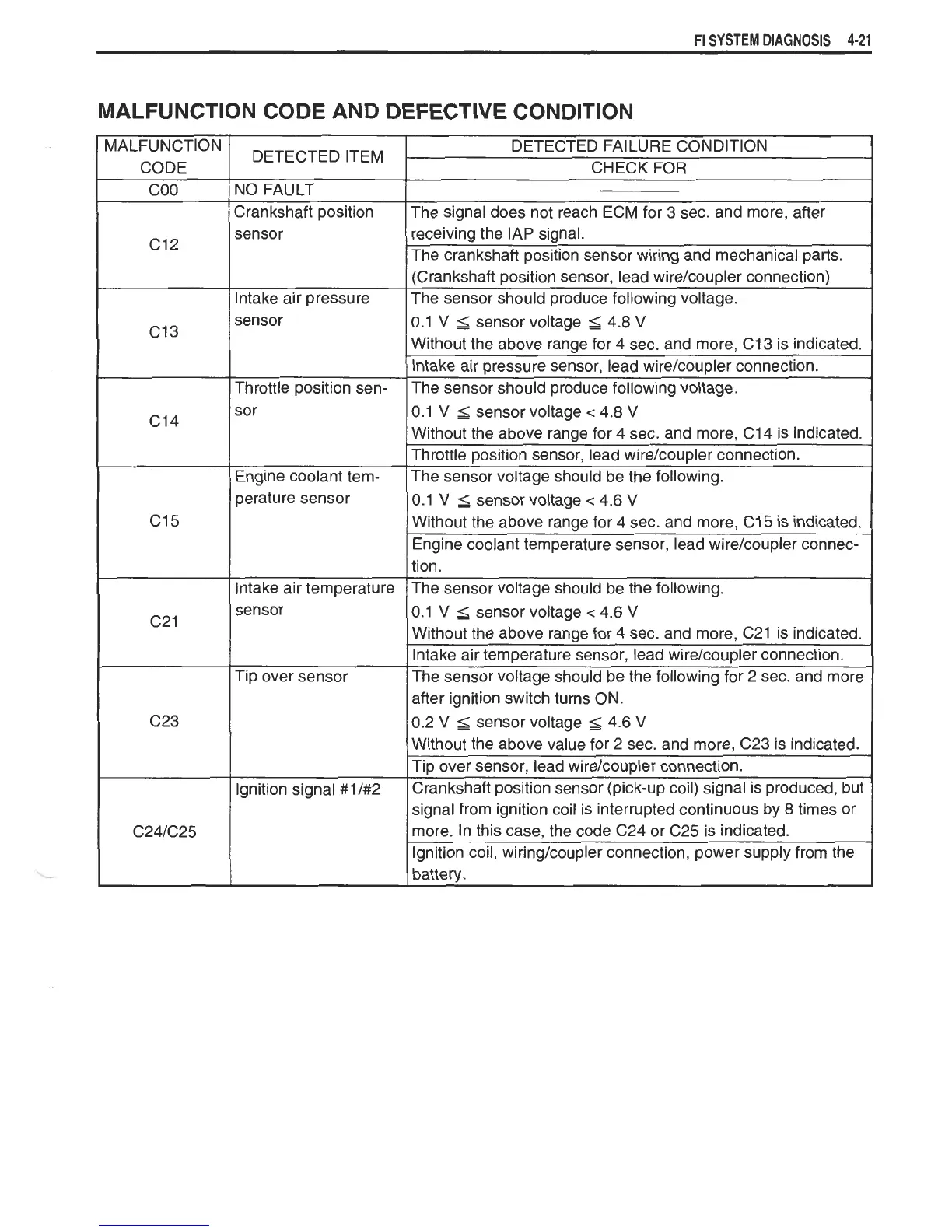
MALFUNCTION CODE AND DEFECTIVE CONDITION
MALFUNCTION
CODE
COO
DETECTED ITEM
DETECTED FAILURE CONDITION
CHECK FOR
I
NO FAULT
Crankshaft position
sensor
The signal does not reach ECM for
3
sec. and more, after
receiving the IAP signal.
The crankshaft position sensor wiring and mechanical parts.
(Crankshaft position sensor, lead wirelcoupler connection)
lntake air pressure
I
The sensor should produce following voltage.
sor
sensor
Throttle position sen-
0.1
V
2
sensor voltage
<
4.8
V
Without the above ranae for 4 sec. and more. C14 is indicated.
0.1
V
5
sensor voltage
5
4.8
V
Without the above range for 4 sec. and more, C13 is indicated.
lntake air pressure sensor, lead wire/coupler connection.
The sensor should produce following voltage.
Engine coolant tern-
s
Throttle position sensor, lead wire/coupler connection.
The sensor voltage should be the following.
perature sensor
sensor
10.1
V
S
sensor voltage
<
4.6
V
0.1
V
$
sensor voltage
<
4.6
V
Without the above ranae for 4 sec. and more, C15 is indicated.
lntake air temperature
I
Without the above ranae for 4 sec. and more. C21 is indicated.
Engine coolant temperature sensor, lead wire/coupler connec-
tion.
The sensor voltage should be the following.
I
after ignition switch turns ON.
Tip over sensor
lgnition signal #11#2
lntake air temperature sensor, lead wirelcoupler connection.
The sensor voltage should be the following for 2 sec. and more
0.2
V
2
sensor voltage
2
4.6
V
Without the above value for
2
sec. and more, C23 is indicated.
Tip over sensor, lead wire/coupler connection.
Crankshaft position sensor (pick-up coil) signal is produced, but
signal from ignition coil is interrupted continuous by
8
times or
more. In this case, the code C24 or C25 is indicated.
Ignition coil, wiring/coupler connection, power supply from the
battery.
 Loading...